Method of operating a multi-phase, high energy flushing system for optimal waste removal and bowl cleaning within a prescribed water consumption range

a flushing system and high energy technology, applied in the field of toilet having operation, can solve the problems of affecting the amount and quality of suitable water, impede the ability to achieve effective flushing, and excessive consumption of potable water, and achieves the effects of improving flushing and cleaning performance, strong flushing performance, and convenient installation, maintenance and transportation

Active Publication Date: 2007-05-24
IDEAL STANDARD INT
View PDF31 Cites 76 Cited by
  • Summary
  • Abstract
  • Description
  • Claims
  • Application Information

AI Technical Summary

Benefits of technology

[0016] It is an advantage of the present invention to provide a flushing system operating method wherein a flushing system uses electricity to energize water and precisely control water flow, thereby elevating flushing and cleaning performance over that of conventional gravity force toilets.
[0017] It is also an advantage of the present invention to provide a flushing system operating method that precisely times jet flow and rim flow during the flush cycle. Existing electronic flushing systems energize water flow that is suboptimal for waste removal and cleanliness within water conservation limits. To address this drawback, the present invention (and toilets employing the present invention) employs effective flow control elements (i.e., rim diverter means and jet diverter means) to switch water flow from a pump to the rim and/or jet. The present invention further employs an electrical pump that is sufficiently large enough to achieve strong flushing performance within prescribed water use limits yet sufficiently small enough for integration in reasonable overall dimensions. Such pump technology is commercially available and successfully operates within the power supply limit of available electrical outlets.
[0018] It is another advantage of the present invention to provide a flushing system operating method wher

Problems solved by technology

The excessive consumption of potable water remains a dilemma for water agencies, commercial building owners, homeowners, residents and sanitaryware manufacturers.
An increasing global population has negatively affected the amount and quality of suitable water.
The significant reduction of available flush water, however, prompted radical design changes to then-existing toilets designs and impeded the ability to achieve an effective flush.
For example, reduction of flush water volume from 3.5 gallons (10 liters) to 1.6 gallons (6.0 liters) in the United States revealed the poor hydraulic design inherent in existing toilets and forced sanitaryware manufacturers to reduce the diameter of the toilet exhaust pipe by up to 1.5″ (3.8 cm).
The reduced exhaust pipe parameter, however, exacerbated clogging and required multiple flushes for complete elimination of waste and surface markings from the bowl interior, thus eliminating any water reduction benefits.
Although the above problems are not applicable to gravity-fed toilets, water restriction regulations also incurred problems in Europe, where such gravity-fed, non-siphoning toilets are configured for installation in floor or wall outlets (thereby ensuring compliance with regional codes).
The small water spot, however, increases the dry surface area of the ceramic bowl that is exposed to soil.
This increased surface area inhibits bowl cleanliness and exacerbates the need for consistent manual bowl cleansing.
A common drawback of conventional gravity-force dynamic toilets is the removal of the majority of water by a strong jet during the flush function.
The powerful jets employed thereby use a significant portion of available water for the flush, leaving a minimal amount of water for a rim wash and correspondingly little capability for sufficient cleaning of the bowl interior.
Such toilets additionally have problems with consistent excess noise during use and often incur uncomfortable splashing of toilet water.
Conversely, line pressure is not immediately available in many markets (and in Europe, legislation exists to prevent the use of line pressure).
In addition, line pressure as an energy source requires use of a heavy a

Method used


Image

  • Method of operating a multi-phase, high energy flushing system for optimal waste removal and bowl cleaning within a prescribed water consumption range
  • Method of operating a multi-phase, high energy flushing system for optimal waste removal and bowl cleaning within a prescribed water consumption range
  • Method of operating a multi-phase, high energy flushing system for optimal waste removal and bowl cleaning within a prescribed water consumption range

Examples


example

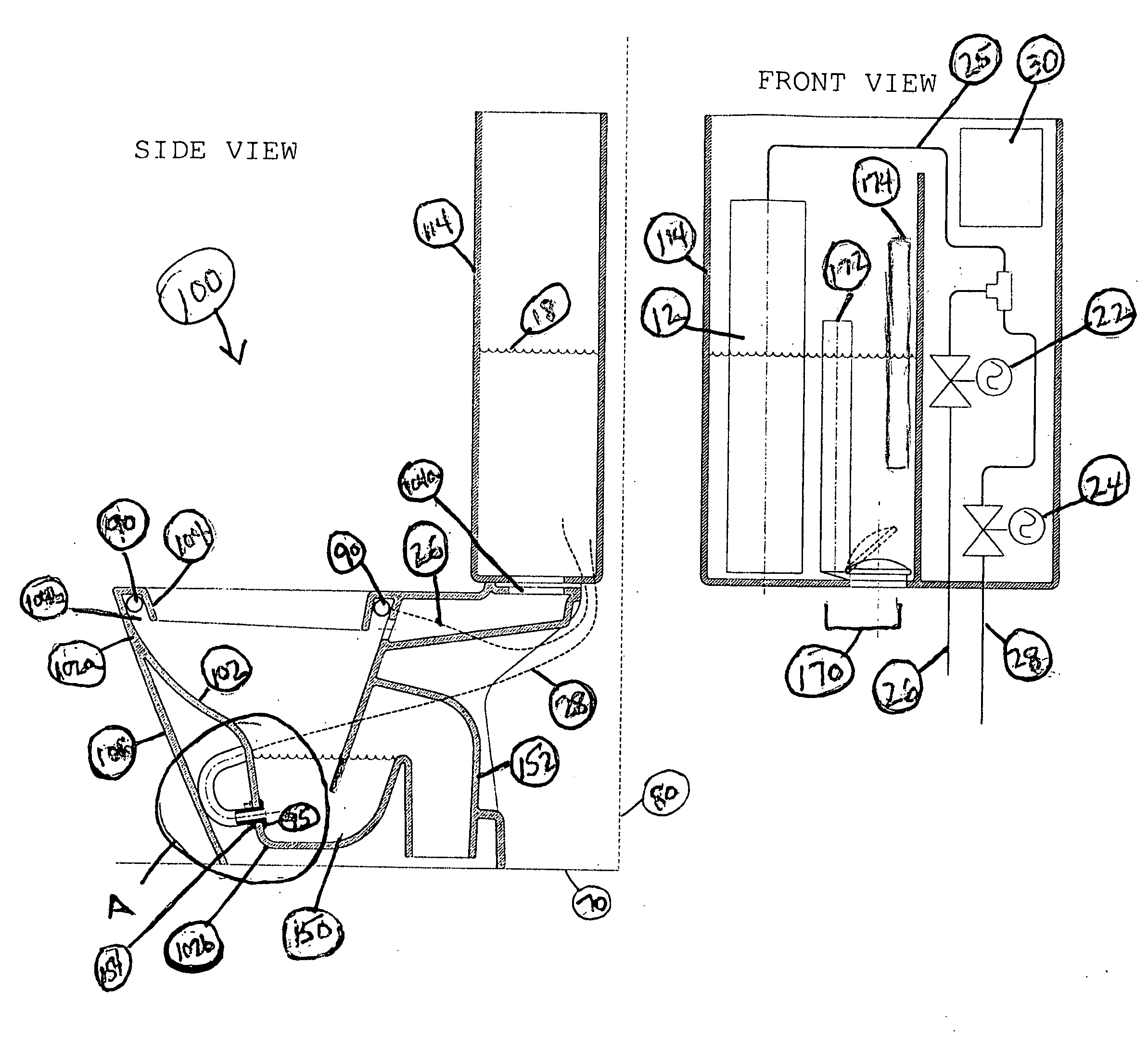
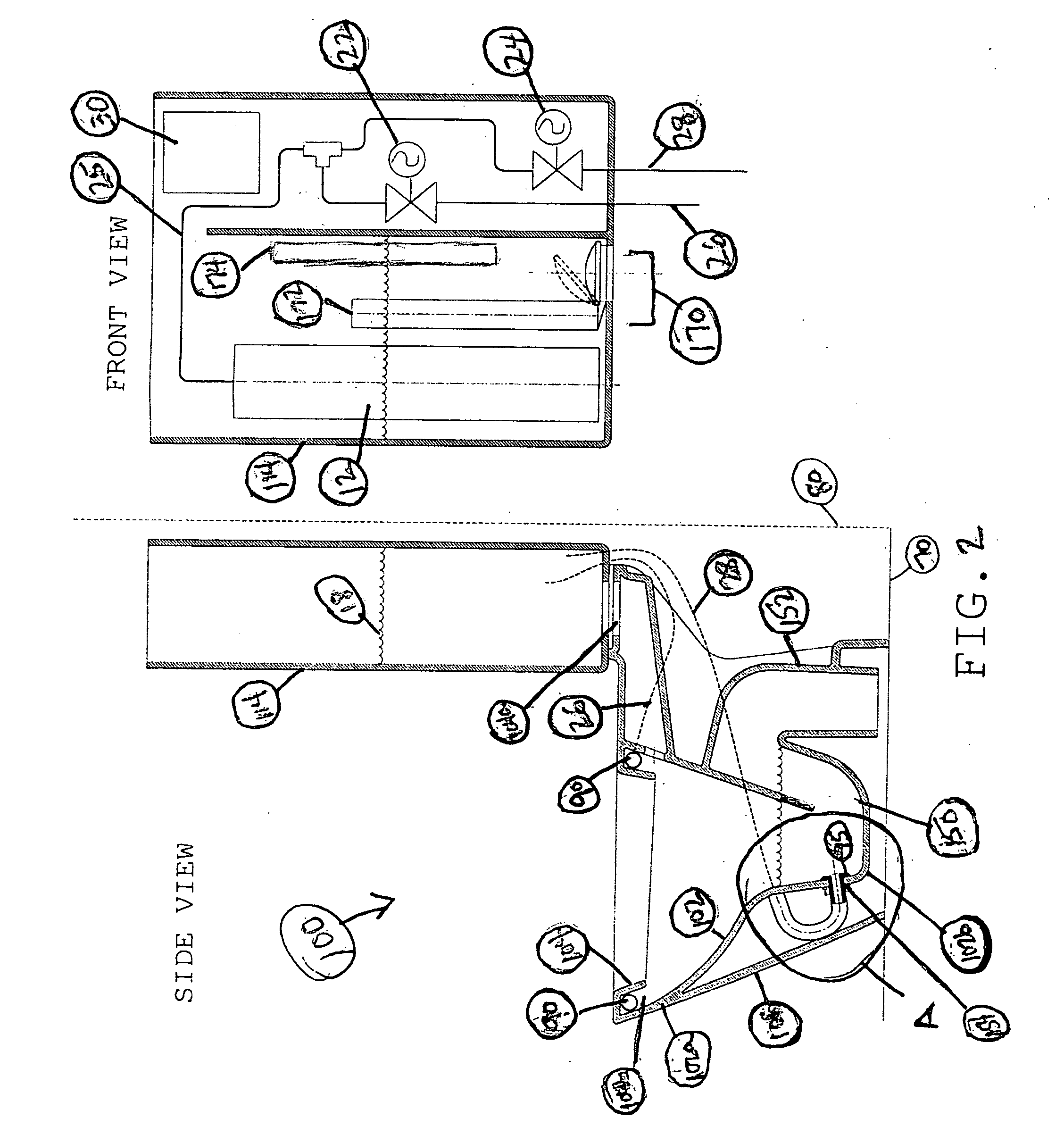
[0083] A prototype toilet was constructed employing the above described concepts in a siphoning toilet of configuration such as toilet 500 shown in FIG. 6. A clear plastic bowl was constructed with a 2¼″ water seal and a water spot of about 10″×8½″. Static water volume in the bowl comprised about 0.53 gallons (2 liters). The exhaust pipe assumed a constant diameter of about 2⅝″ with a shape identical to that disclosed by Applicant's U.S. Pat. No. 6,728,975 and Applicant's pending application Ser. No. 10 / 231,977 (the entire contents of both disclosures being incorporated by reference herein). The rim was provided with six spray nozzles positioned equidistantly along the periphery thereof. A pair of commercially available solenoid valves was provided for the rim diverter means and the jet diverter means. The storage tank was not under line pressure.

[0084] A pump was selected from one of a plurality of commercially available pumps such as pumps sold by Granger having the following par...


PUM


Abstract

The present invention provides a method of operating a flushing system for efficient waste removal from and cleaning of a toilet bowl. In the disclosed method, a flushing system is provided that includes a pumping means having each of a rim diverter means and a jet diverter means in fluid communication therewith; a sensor means; a control means; a switching means; and a spray means. Activation of the switching means initiates at least a single flush schedule that comprises the steps of initiating operation of the pumping means; opening the jet diverter means for delivery of water to a jet delivery means in fluid communication therewith; subsequently closing the jet diverter means and simultaneously opening the rim diverter means; and directing water from the rim diverter means to a toilet rim in fluid communication therewith for terminal delivery of the water through the spray means.

Description

[0001] This application claims the priority of U.S. Provisional Application No. 60 / 738,643, filed Nov. 21, 2005, and incorporated by reference herein.FIELD OF THE INVENTION [0002] The present invention is directed to operation of a toilet having multi-phase, high energy flushing operations for optimum bowl cleanliness. In particular, the present invention is directed to a method of operating a flushing system that reliably and predictably removes a maximum load of liquid and solid waste from a toilet bowl and effectively removes stains from a bowl surface thereafter. The present invention method employs a flushing system that accomplishes these functions without clogging of the toilet exhaust pipe and with minimal expenditure of water and energy. BACKGROUND OF THE INVENTION [0003] The excessive consumption of potable water remains a dilemma for water agencies, commercial building owners, homeowners, residents and sanitaryware manufacturers. An increasing global population has negati...

Claims


Application Information

Patent Timeline
IPC IPC(8): E03D11/18E03D11/02
CPCE03D5/01E03D11/08E03D2201/30
Inventor PROKOPENKO, ALEKSANDRHEATON, MICHAELPRESIREN, PIERPAOLOFLORIDUZ, ANTONIO
Owner IDEAL STANDARD INT
Why Eureka
Try Eureka