Integral lint filter for clothes dryers

a technology for clothes dryers and filters, applied in drying machines, drying chambers/containers, light and heating apparatus, etc., can solve the problems of limiting the placement of exhaust conduits, difficult access, and clogging of extension conduits, etc., and achieve the effect of preventing lint deposits

Inactive Publication Date: 2007-05-24
BELGARD RICHARD A
View PDF14 Cites 50 Cited by
  • Summary
  • Abstract
  • Description
  • Claims
  • Application Information

AI Technical Summary

Benefits of technology

[0018] According to one aspect of the present invention, a gas-exhaust assembly for a clothes dryer system is provided. The gas-exhaust assembly includes a primary lint filter, two or more conduit sections, and a secondary lint filter, including a conduit adapter or adapter assembly and a filtering element. The gas-exhaust assembly is characterized, in one embodiment, in that the secondary lint filter is removably connected inline between conduits substantially at the point of communication of the exhaust gases through a wall or floor to the outside, the filter element not exceeding the conduit size in diameter.
[0019] In one embodiment of this aspect, the adapter or adaptor assembly includes a filter support ring aligned in a substantially concentric arrangement therewith and supported in position by three or more support ribs. In one embodiment, the filtering element includes a flange supporting the filtering element, the flange installable to the conduit adapter or adaptor assembly. In a variation of this embodiment, the flange is collapsible and memory resilient.
[0020] According to another aspect of the present invention, a method is provided for preventing lint deposits on conduit of an exhaust system generic to a clothes dryer during a drying cycle. The method includes the acts (a) collecting lint onto a first lint filtering device, and (b) collecting lint escaping the first filtering device onto a second filtering device. The second filtering device includes a conduit adaptor or conduit adaptor assembly, and a filtering element. In a preferred aspect, in act (b), the filtering element does not exceed the conduit adapter or conduit adapter assembly in diameter.

Problems solved by technology

The physical space allocated for the clothes dryer often restricts the placement of the exhaust conduit.
Sometimes the extension conduit is routed in a way to make it unobtrusive, and, as a consequence, difficult to access.
Since lint and other materials are typically moist, those that escape the filter have a tendency to adhere to the walls of the extension conduit.
Over time the extension conduit may eventually become clogged.
Flexible conduit is corrugated and is particularly prone to lint buildup.
As is generally accepted in the art, a build-up of lint and / or other particulate material in the extension conduit not only decreases the efficiency of the clothes dryer by reducing moist air flow, it also can sufficiently interrupt the air flow such that the heat and heated air, alone or in combination with built-up lint, becomes a fire hazard.
Due to the fineness of the mesh and of the material, these lint filters may eventually become perforated during manual lint removal and these lint filters can become perforated or destroyed.
Furthermore, although the existing lint filter removes much of the lint and other material in moist exhaust air, it does not remove all of it.
Over time, substantial buildup of lint and other material may clog the extension conduit causing interrupted airflow, poor drying efficiency, or even a fire.
One problem with the receptacle of Barnes is that the area of filtration is much larger than the standard inside diameter of the hose causing an interruption or a weakening in airflow in the exhaust system.
Another problem with the receptacle of Barnes is that is requires physically mounting the receptacle to a wall through which an egress path is planned.
Barnes also brings to light several other references to U.S. patents that employ some type of filtering scheme for exhaust air emanating from a dryer however, all of those devices are complex with more than one moving part, and must be assembled, or otherwise require much work and attention to operate correctly.
Further problems exist in that the receptacle of Barnes and those systems referenced by Barnes are not installable in a fashion that might be convenient for a user given the typically restricted space between the back wall of clothes dryer and the opposing house or building wall that the dryer is positioned in front of.

Method used


Image

  • Integral lint filter for clothes dryers
  • Integral lint filter for clothes dryers
  • Integral lint filter for clothes dryers

Examples


Embodiment Construction

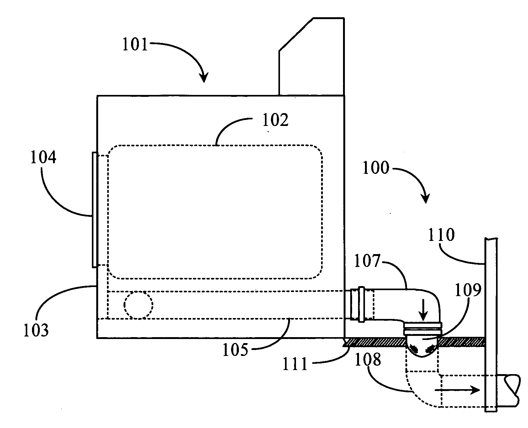
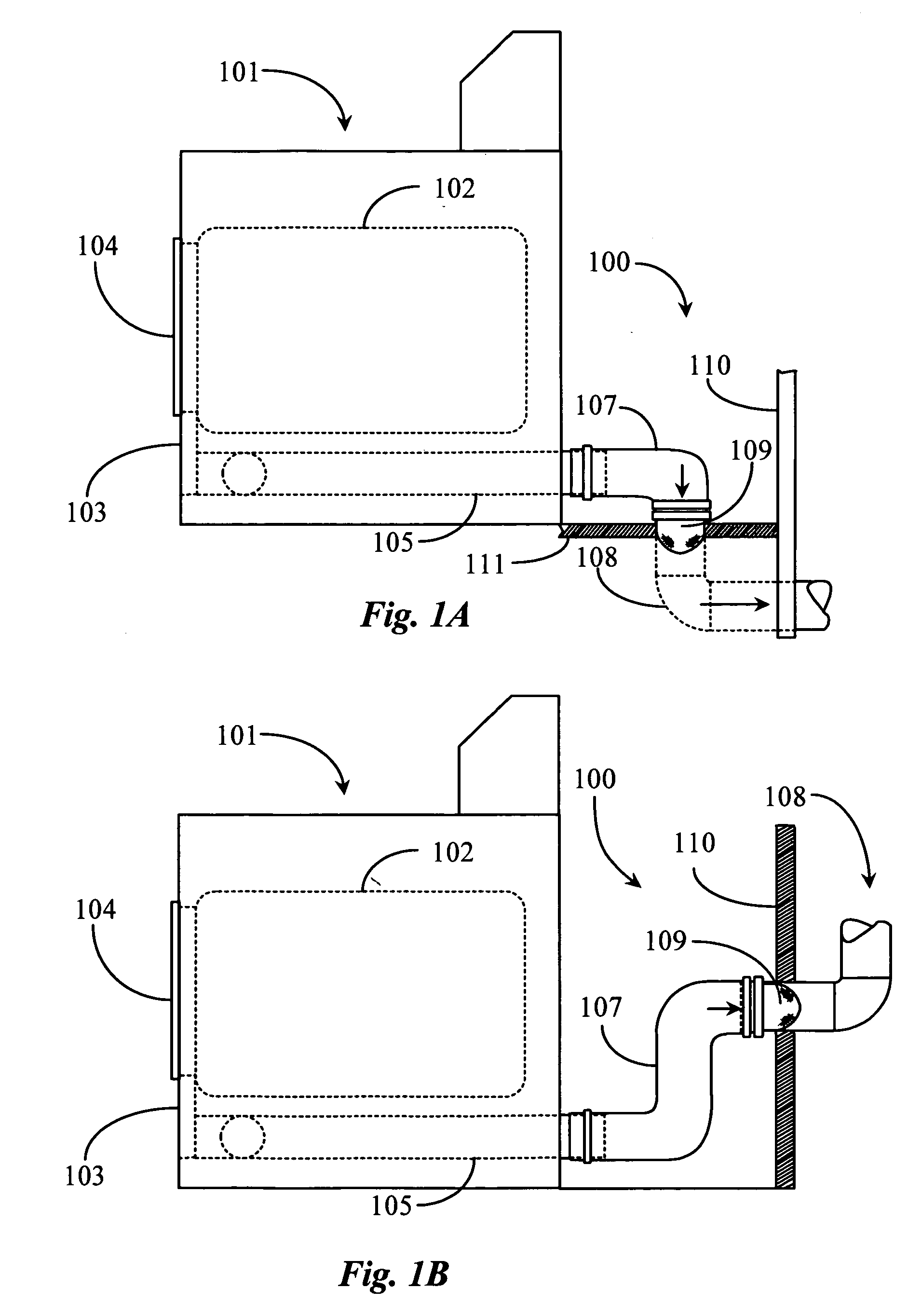
[0028]FIG. 1A is a side view of a clothes dryer 101 and exhaust system 100 enhanced with an integral lint filter 109 according to an embodiment of the present invention.

[0029]FIG. 1B is a side view of the system of FIG. 1A with an alternate conduit exhaust path.

[0030] Referring now to FIG. 1A, a typical implementation for clothes dryer system 101 is illustrated in this example. The implementation includes clothes dryer system 101 strategically placed next to a building wall 110. This implementation is typical of a washroom or other semi-enclosed building space adapted with the proper outlets plumbing and exhaust portage for accommodating a washer and dryer system. It may be appreciated by one with skill in the art of typical implementations that the space afforded between system 101 and wall 110 to accommodate exhaust assembly 100 is most often very minimal. Therefore, it is an object of the present invention to provide a secondary filtering device that may be easily installed and...


PUM


Abstract

A lint filter assembly for removing lint and particulate matter from a clothes dryer exhaust system includes a conduit adapter and a filtering element. In a preferred embodiment the lint filter is a secondary filter removably connected inline between conduits substantially at the point of communication of the exhaust gases through a wall or floor to the outside, the filter portion not exceeding the conduit size in diameter.

Description

CROSS-REFERENCE TO RELATED APPLICATIONS [0001] The present application claims priority to provisional application Ser. No. 60 / 739,328 filed on Nov. 23, 2005.BACKGROUND OF THE INVENTION [0002] 1. Field of the Invention [0003] The present invention is in the field of mechanical dryer utilities and pertains particularly to configurations providing secondary filters including lint traps used in clothes dryer systems. [0004] 2. Discussion of the State of the Art [0005] Contemporary clothes dryer systems are well known in the art and generally embody a cabinet type utility having a front wall, rear wall, opposing sidewalls, top wall, and, optionally, a bottom wall. Clothes dryers are available in electrical models, in which heat is generated via a resistance element or via a “heat pump” method. Clothes dryers are also available such that heat is generated by a gas combustion chamber. In either case, a drum is typically provided for containing the clothes to be dried. In process, the drum ...

Claims


Application Information

Patent Timeline
Patent Type & Authority Applications(United States)
IPC IPC(8): F26B21/06F26B11/02
CPCD06F58/22
Inventor BELGARD, RICHARD A.
Owner BELGARD RICHARD A
Why Eureka
Try Eureka