Cannula-tip shielding mechanism

a shielding mechanism and needle tip technology, applied in the field of vascular access devices, can solve the problems of affecting the safety of patients, and presenting numerous potential hazards to the operator and others in the area, so as to achieve the effect of safe disposal

Active Publication Date: 2010-09-23
BECTON DICKINSON & CO
View PDF50 Cites 35 Cited by
  • Summary
  • Abstract
  • Description
  • Claims
  • Application Information

AI Technical Summary

Benefits of technology

[0020]Once the needle feature contacts the needle-feature capture mechanism and the needle continues to be pulled proximally, the force between the needle and the inner housing becomes greater than the force between the inner housing and the outer housing. Accordingly, the proximal force on the needle causes the inner housing to translate proximally with respect to the outer housing. Once the inner housing is moved to the proximal position, the interlock features are allowed to move to the unengaged position. When the interlock features are released from the engaged position, the shielding mechanism can be extracted from the catheter adapter with little to no friction between interlock features and the interior surface of the adapter. Moreover, with the needle tip trapped within the inner housing and the outer housing uncoupled from the catheter adapter, the needle and shielding mechanism can be disposed of safely.

Problems solved by technology

The separation of the introducer needle assembly from the catheter portions of the catheter assembly presents numerous potential hazards to the operator and others in the area.
Indeed, as indicated above, there is a risk of accidental needle sticks if the needle tip is not secured properly in a needle tip cover.
Additionally, because the needle tip shield is often frictionally engaged within a catheter adapter, an operator may need to jerk or forcefully pull the needle tip shield from the catheter adapter.
This jerking and pulling movement may cause discomfort to the patient.
As the needle is withdrawn from the catheter, there is a risk that this blood will drip from the needle tip or come into contact with other surfaces to expose people and equipment to blood.

Method used


Image

  • Cannula-tip shielding mechanism
  • Cannula-tip shielding mechanism
  • Cannula-tip shielding mechanism

Examples


Embodiment Construction

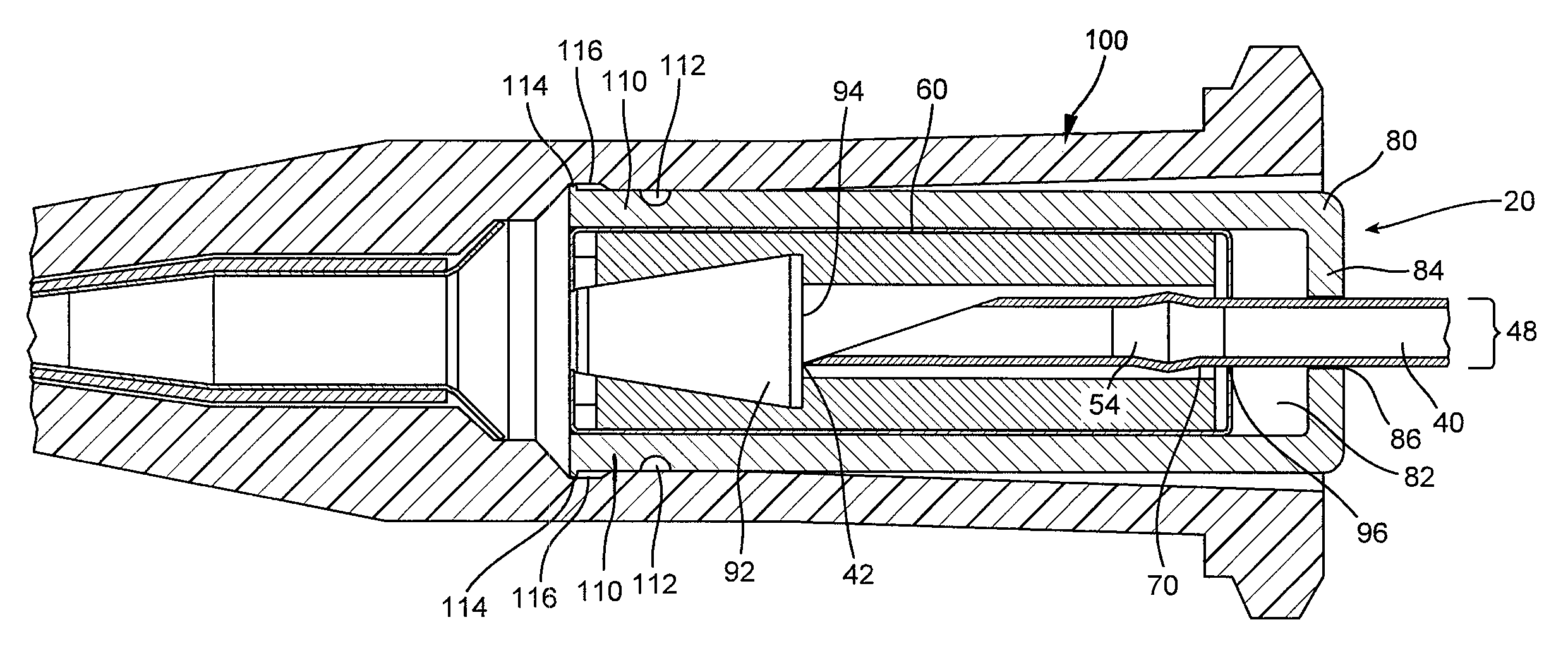
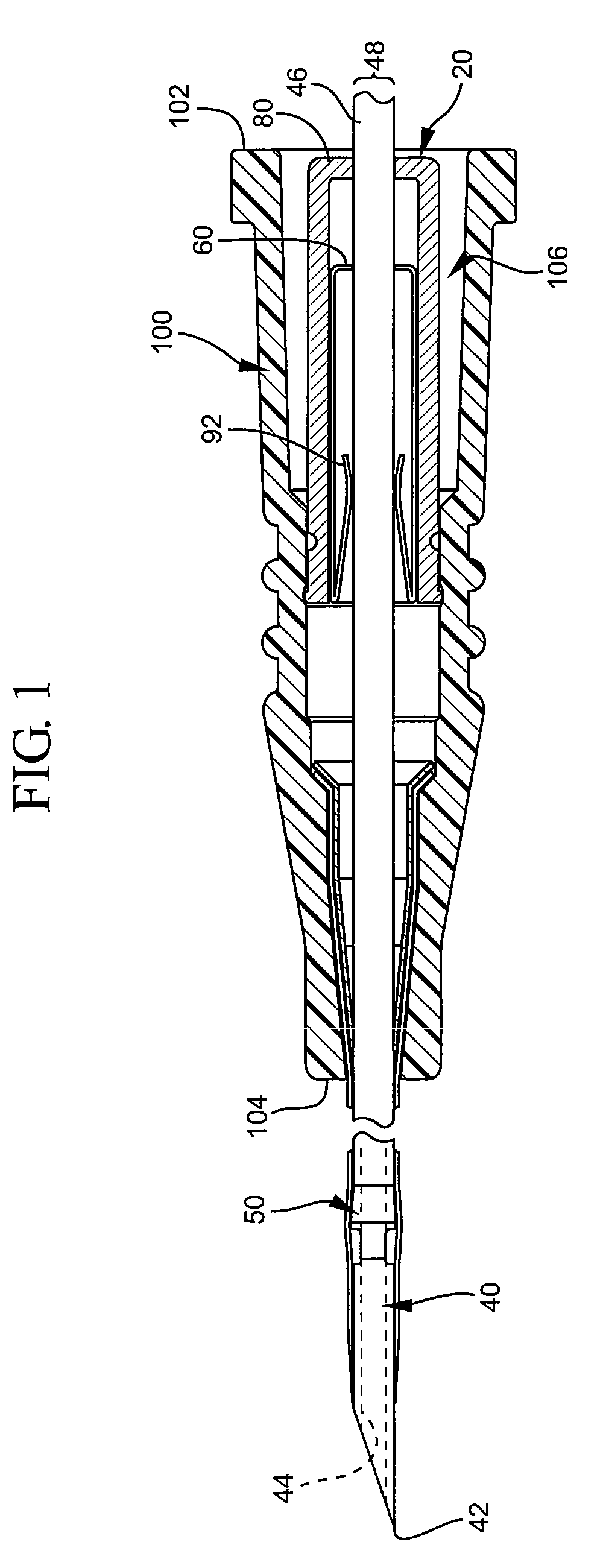
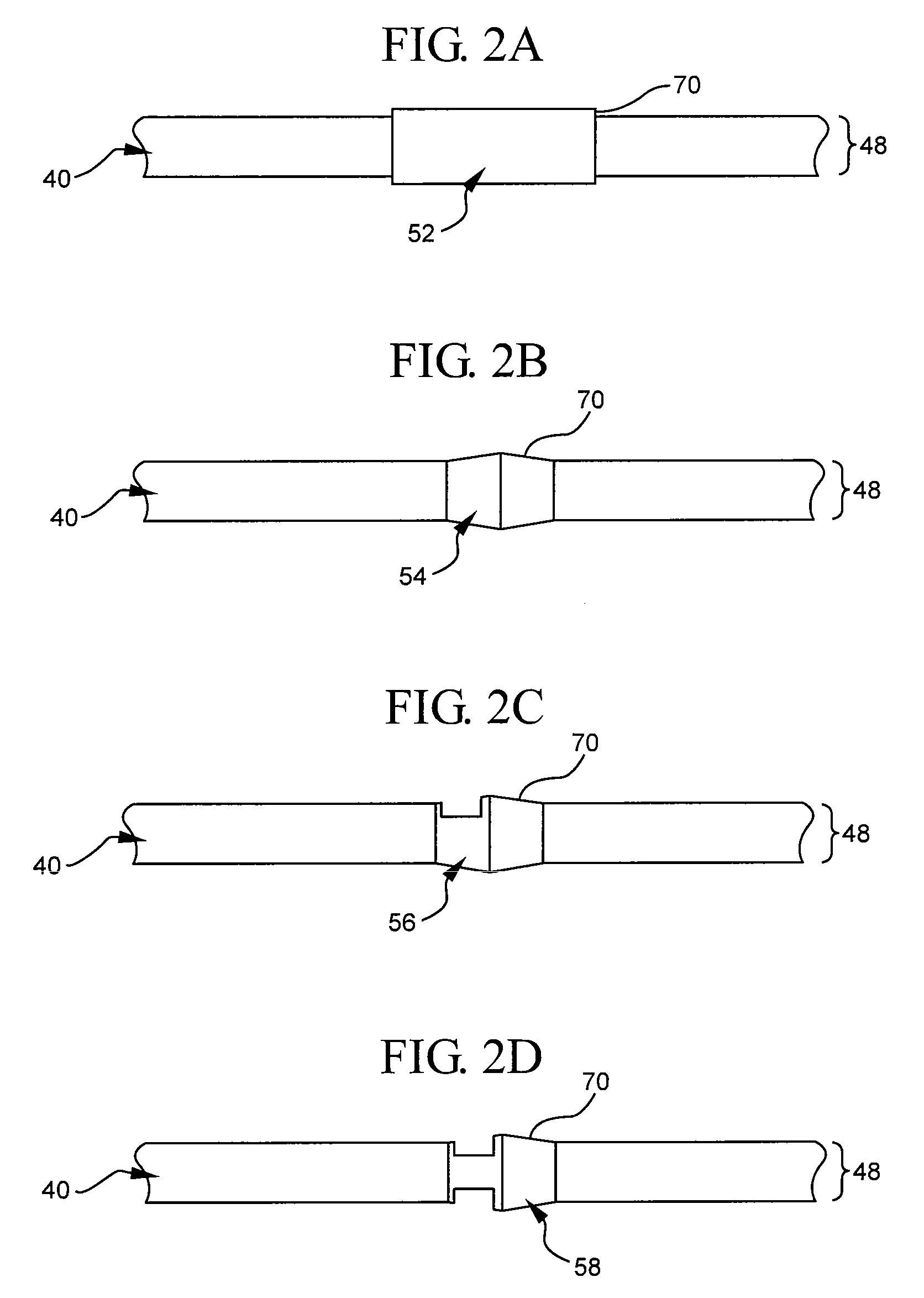
[0031]The presently preferred embodiments of the described invention will be best understood by reference to the Figures, wherein like parts are designated by like numerals throughout. It will be readily understood that the components of the present invention, as generally described and illustrated in the Figures herein, could be arranged and designed in a wide variety of different configurations. Thus, the following more detailed description of the embodiments of the needle-tip shielding mechanism, as represented in FIGS. 1 through 9, is not intended to limit the scope of the invention, as claimed, but is merely representative of some presently preferred embodiments of the invention.

[0032]The present invention relates to a needle-tip shielding mechanism. Generally, the shielding mechanism allows the needle to be moved from an unshielded position in which the needle tip is exposed from the shielding mechanism, to a shielded position in which the needle tip is both covered by the shi...


PUM


Abstract

A needle tip shielding mechanism is described herein. The shielding mechanism comprises an outer housing, an inner housing, and a needle having a needle feature. Generally, the outer housing comprises at least one adapter-interlock feature. Moreover, the inner housing comprises a needle-feature capture mechanism, such as a washer feature, and a needle-tip capture mechanism, such as duckbilled tip barrier. In some cases, the inner housing is slidably moveable within the outer housing. In such cases, the inner housing is movable between a first position that biases the adapter-interlock feature into an engaged position and a second position that allows the adapter-interlock feature to move to an unengaged position. This ability to bias the interlock feature in the engaged position and to allow the interlock feature to move to the unengaged position allows the shielding mechanism to be selectively coupled to and released from an interlock-feature mating component within a catheter adapter.

Description

BACKGROUND OF THE INVENTION[0001]This invention relates generally to vascular access devices and associated methods. More specifically, this invention relates to a needle-tip shielding mechanism having an interlock system that allows the shielding mechanism to be selectively coupled to a catheter adapter. The interlock system also allows the shielding mechanism to be selectively released and removed from the adapter with little to no friction between the interlock system and the adapter.[0002]Generally, vascular access devices are used for communicating fluid with the vascular system of patients. For example, catheters are used for infusing fluid (e.g., saline solution, medicaments, and / or total parenteral nutrition) into a patient, withdrawing fluids (e.g., blood) from a patient, and / or monitoring various parameters of the patient's vascular system.[0003]Intravenous (IV) catheter assemblies are among the various types of vascular access devices. Over-the-needle peripheral IV cathet...

Claims


Application Information

Patent Timeline
Patent Type & Authority Applications(United States)
IPC IPC(8): A61M5/00
CPCA61M5/3273A61M2005/3226A61M25/0618A61M25/0612
Inventor MOULTON, WILLIAM G.
Owner BECTON DICKINSON & CO
Why Eureka
Try Eureka