Washing and drying machine and clothes dryer

a technology for washing machines and clothes, which is applied in the direction of washing machines with receptacles, lighting and heating apparatus, furnaces, etc. it can solve the problems of affecting the fragrance, the irradiation is not very pleasant, and the clothes are naturally damaged, so as to achieve the effect of degrading clothes

Inactive Publication Date: 2007-05-24
SHARP KK
View PDF23 Cites 56 Cited by
  • Summary
  • Abstract
  • Description
  • Claims
  • Application Information

AI Technical Summary

Benefits of technology

[0047] As described above, according to one aspect of the present invention, degradation of clothes can be prevented and fragrance close to that attained by sun-drying can be added to the clothes. According to another aspect, the sun-dried-like fragrance can be enjoyed when clothes are taken out from the washing and drying machine and from the clothes dryer.

Problems solved by technology

In the clothes dryer, however, ultra-violet ray is emitted for sterilization of the clothes, and therefore, it is necessary to irradiate the clothes with ultra-violet ray for a long time at a high temperature.
Though highest effect of sterilization can be attained when the clothes are irradiated with ultra-violet ray from before the reduced rate drying step until the end of drying, it is described in this laid-open application that such a manner of irradiation is not very preferable considering damage to the clothes and efficiency of operation.
When exposed to the ultra-violet ray for a long time, clothes are naturally damaged, which may possibly affect the fragrance.
As described above, however, clothes and washing tank are damaged when the clothes are irradiated with ultra-violet ray.
From this result, it can be concluded that UVC wave irradiation potentially damages fibers.
When the dried object is taken out from the rotary tank at the end of drying process and the temperature of the object is too high or too low, the sun-dried feeling cannot be enjoyed.

Method used


Image

  • Washing and drying machine and clothes dryer
  • Washing and drying machine and clothes dryer
  • Washing and drying machine and clothes dryer

Examples


first embodiment

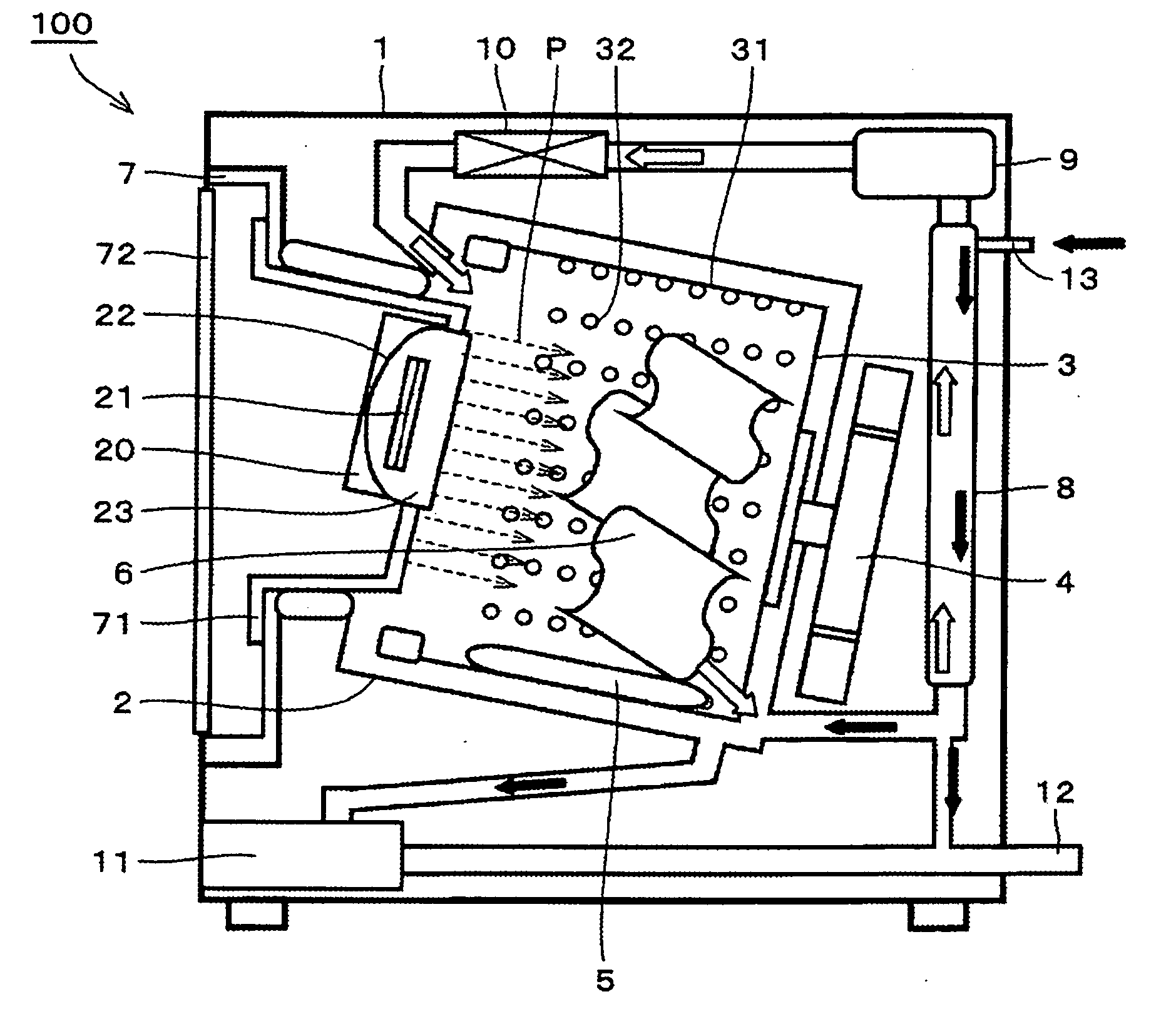
[0069]FIG. 1 is a cross-sectional side view representing a schematic structure of a washing and drying machine in accordance with a first embodiment. As shown in FIG. 1, a washing and drying machine 100 includes a main body 1, a water tank 2 provided in main body 1 and a rotary drum 3 rotatably supported in water tank 2.

[0070] At the bottom of rotary drum 3, a rotating mechanism portion is provided for rotating rotary drum 3 forward and backward by means of a motor 4. A baffle 5 for tumbling clothes in rotary drum 3 is mounted on an inner circumferential wall surface of rotary drum 3. Further, on an outer circumferential wall surface of rotary drum 3, a number of small through holes 32 are formed, reaching the inside of rotary drum 3, to enable passage of water in rotary drum therethrough for spin-drying the clothes 6. A door unit 7 is provided to open / close the opining of rotary drum 3, for putting in and taking out clothes and for keeping the drum air-tight and water-tight. Door ...

second embodiment

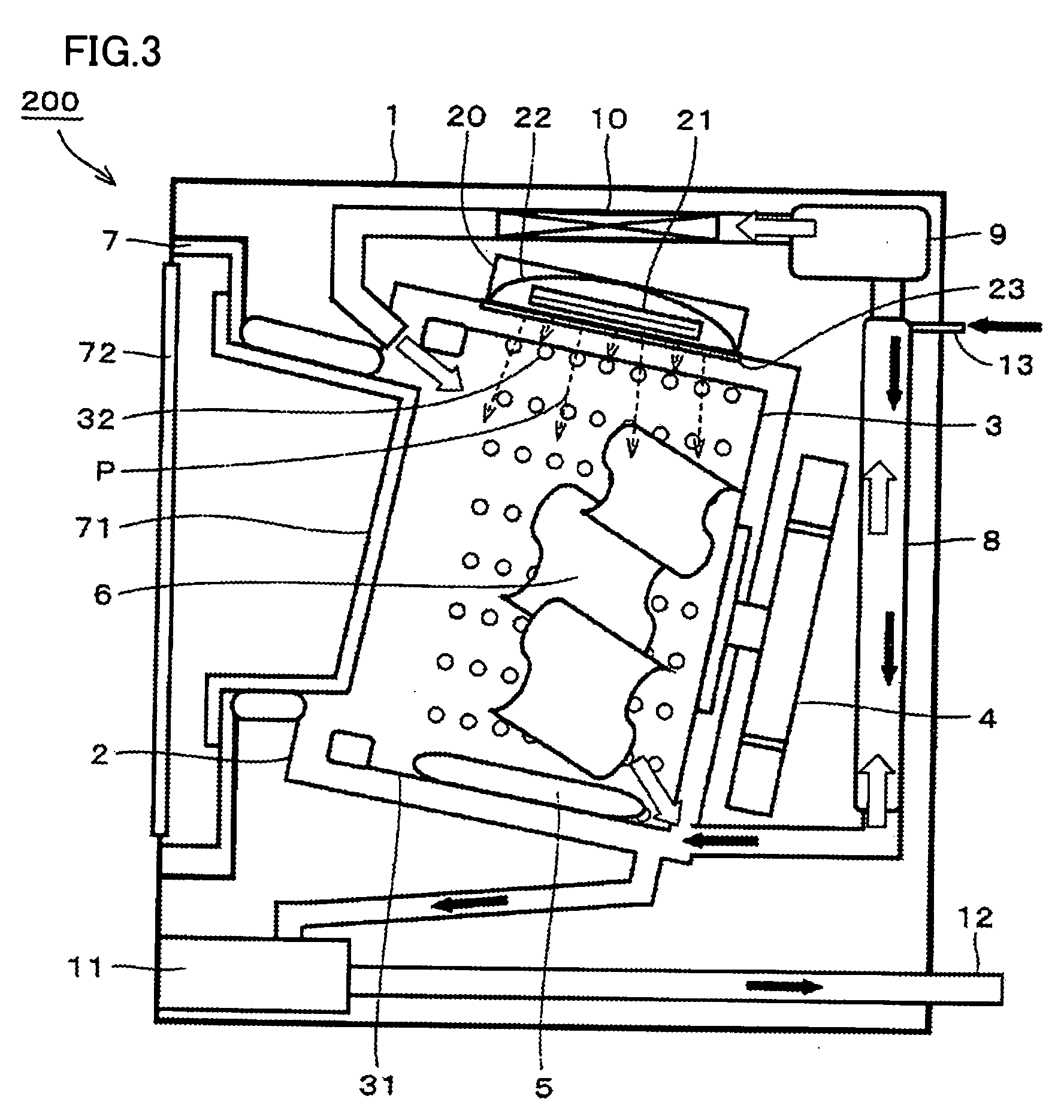
[0092]FIG. 3 is a cross-sectional side view representing a schematic structure of a washing and drying machine in accordance with a second embodiment of the present invention.

[0093] A washing and drying machine 200 in accordance with the present embodiment is a modification of washing and drying machine 100 of the first embodiment.

[0094] When irradiating light source 21 emits a light beam covering the wavelength range from visible light to infrared ray, it means that irradiating light source 21 also emits heat wave. Therefore, it is possible that clothes 6 at a position close to light irradiating unit 20 are locally heated in washing and drying machine 100 shown in FIG. 1. In order to solve this problem, in washing and drying machine 200 having the main structure similar to that shown in FIG. 1, light irradiating unit 20 is mounted on water tank 2, as shown in FIG. 3. Light irradiating unit 20 includes an irradiating light source 21 for emitting a light beam including ultra-violet...

third embodiment

[0100]FIG. 5 is a cross-sectional side view representing a schematic structure of a drum type washing and drying machine in accordance with a third embodiment of the present invention. Referring to FIG. 5, a washing and drying machine 1100 includes a microcomputer (hereinafter referred to as “micon”) 120 controlling various operations of the washing and drying machine. Washing and drying machine 1100 includes a water tank 107, a motor 109, a washing tank 106 coupled to the motor and supported rotatably, a rotary mechanism for rotating washing tank 106 forward / backward by motor 109, a baffle 110 mounted in washing tank 106 for turning the laundry, an air-tight and water-tight door unit 113 for putting in and taking out clothes 112, and a door lock 140 locking the door unit in the closed state.

[0101] Door unit 113 includes a light irradiating unit 103, a door glass 113A provided so that the condition of clothes 112 is visible from the outside, and a front door 113B.

[0102] Further, l...


PUM


Abstract

A washing and drying machine includes a water tank, a rotary drum, an irradiating light source and control means. The rotary drum is rotatably supported in the water tank. The irradiating light source is for emitting a light beam including ultra-violet ray to the inside of the rotary drum. The control means controls the irradiating light source such that the light beam including the ultra-violet ray is emitted to the inside of the rotary drum after the end of the drying process.

Description

TECHNICAL FIELD [0001] The present invention relates to a washing and drying machine and to a clothes dryer. More specifically, according to one aspect, the present invention relates to an improvement of an apparatus for providing fragrance to clothes dried by the washing and drying machine, and according to another aspect, the present invention is directed to a washing and drying machine and a clothes dryer that can provide clothes finished as if they were sun-dried, at the end of the drying step. BACKGROUND ART [0002] A clothes dryer drying clothes as an object has been conventionally known. Further, a washing and drying machine that washes and dries clothes in one rotating tank has also been known. [0003] In connection with the one aspect, a clothes dryer having a device for irradiating the clothes with ultra-violet ray has been proposed, as disclosed, for example, in Japanese Patent Laying-Open No. 2-57300. The clothes dryer includes a rotary drum turning the clothes, a circulat...

Claims


Application Information

Patent Timeline
Patent Type & Authority Applications(United States)
IPC IPC(8): F26B3/34F26B11/02D06F33/02D06F25/00D06F39/14D06F58/02D06F58/20D06F58/28
CPCD06F25/00D06F37/10D06F58/203D06F39/14D06F58/20D06F39/00D06F58/44D06F34/26D06F2105/44D06F33/65D06F2105/38D06F2103/32
Inventor UHARA, HIROKOTAKAGI, SHINYANISHIYAMA, MASAHIRO
Owner SHARP KK
Why Eureka
Try Eureka