
Marine safety ladder

Inactive Publication Date: 2007-05-24
MARINE WORKS
View PDF9 Cites 9 Cited by
  • Summary
  • Abstract
  • Description
  • Claims
  • Application Information

AI Technical Summary

Benefits of technology

[0030] Because the safety ladder according to the present utility model is constructed as described above, it has the following effects: since the safety ladder is stowed within the width of the deck of a floating pier or within the width of the transom step of a boat, when it is not being used to rescue someone who has fallen in the water, the safety ladder is normally stowed under the deck and does not protrude from the side of the deck; as a result, there is no risk of mutual damage by contact with a pleasure boat or the like, and additional concern over avoiding such contact in the docking or departure of a pleasure boat or the like is prevented.
[0031] In addition, since the safety ladder according to the present utility model is normally stowed under the deck, it does not get in the way of ordinary use of a boat or a floating pier; and if it is installed and stowed at a plurality of suitable locations along a floating pier, it can be a marine safety ladder that can be used a short time after an accident occurs.
[0032] The marine safety ladder according to the present utility model is basically designed so as to be operated by a person who has fallen into the water. However, since it can also be operated by a person on the deck, a person in the water can be aided very rapidly.
[0033] Also, because the top hinge member, the middle hinge member, and the bottom hinge member are supported by integral support members, the work of mounting (co

Problems solved by technology

Similar accidents would occur on pleasure boats when people fall off the transom step.
Because the conventional floating pier safety ladders are constructed as described above, they have the drawbacks as follows: In the safety ladder disclosed in Japanese Patent Application Laid-Open (Kokai) 2000-144633, because the safety ladder is always attached to the side of the deck of a floating pier, even though it is provided at a location a specific distance away from the location where a cleat is attached, there is still the possibility that it could come into contact with a pleasure boat or the like, thus damaging the both.
However, this fender member itself is an extra member of the safety ladder; and because it protrudes horizontally from the side of the deck, avoiding contact with it is another source of concern in the operation of pleasure boats and so forth during docking and departure.
In addition, the safety ladder is divided into an upper ladder and a lower ladder, and the lower ladder is designed so that it can be stowed in the upper ladder through a latching means, so that a person who has made his or her way to the safety ladder would release the latching means and extend the lower ladder down into the water so as to climb out; however, there is such a danger that the lower ladder would suddenly drop down and extend once the latching means is released and that a person in the water who has made his or her way to that area and released the latching means would be hit by the lower ladder and sustain an injury.
Furthermore, after use, a person needs to descend using the upper ladder, pull up the lower ladder, and operate a latching means at the bottom of the upper ladder to stow the lower ladder in the upper ladder; however, this work carries a high risk of the person falling into the water.
Therefore, it takes quite some time after an accident to go from the vicinity of the accident site to the place where the safety ladder is installed.

Method used


Image

  • Marine safety ladder
  • Marine safety ladder
  • Marine safety ladder

Examples


Embodiment Construction

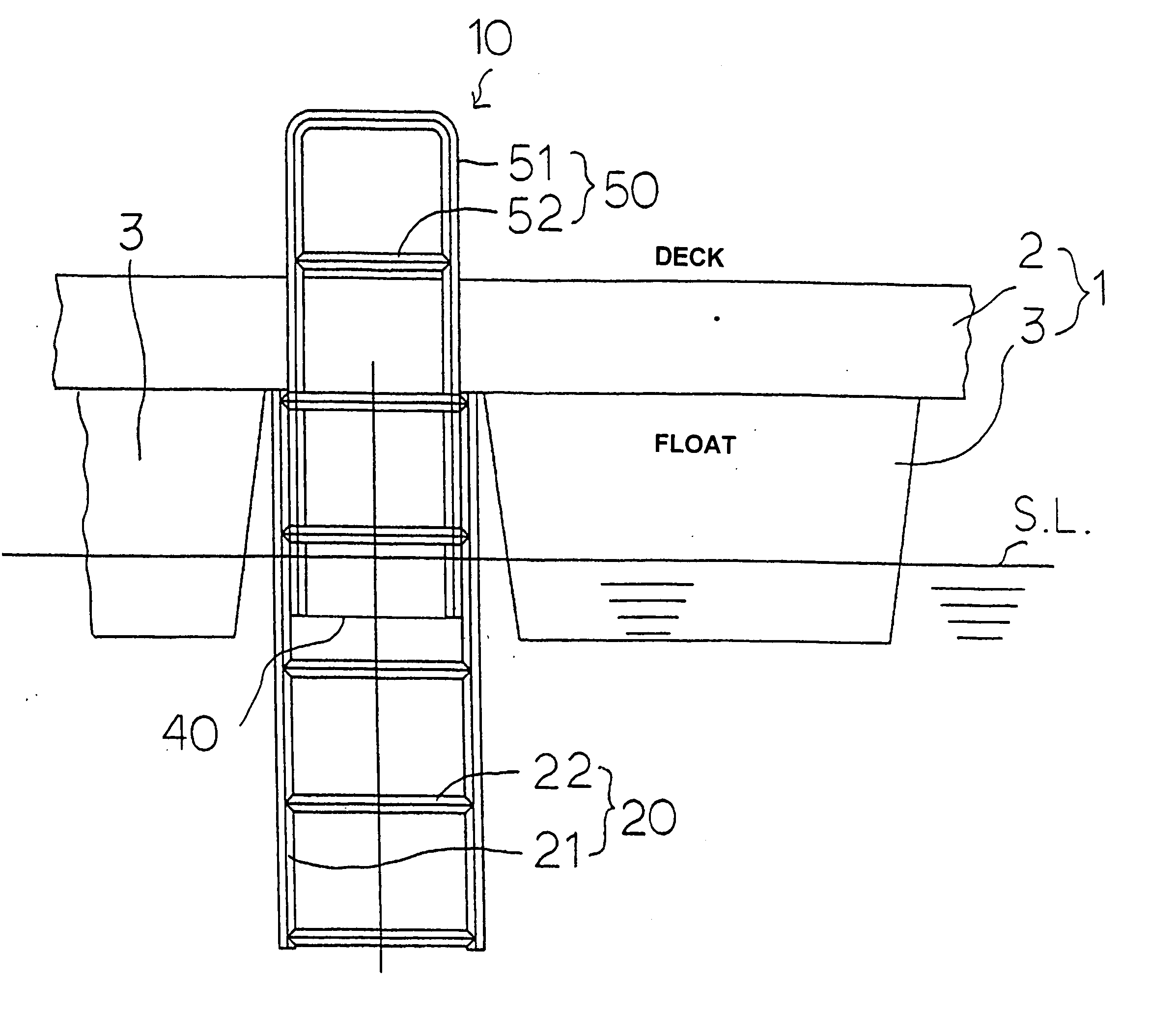
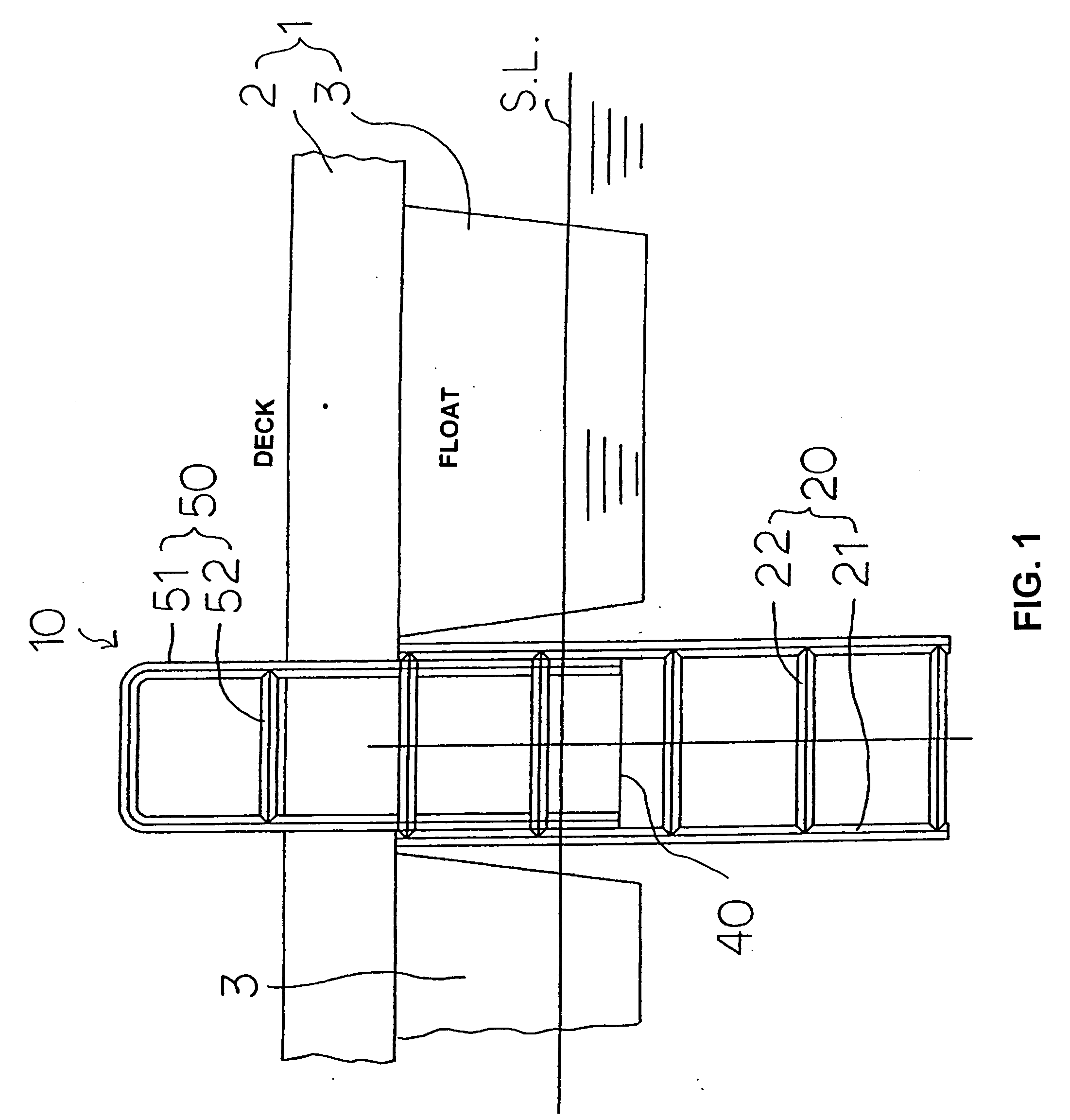
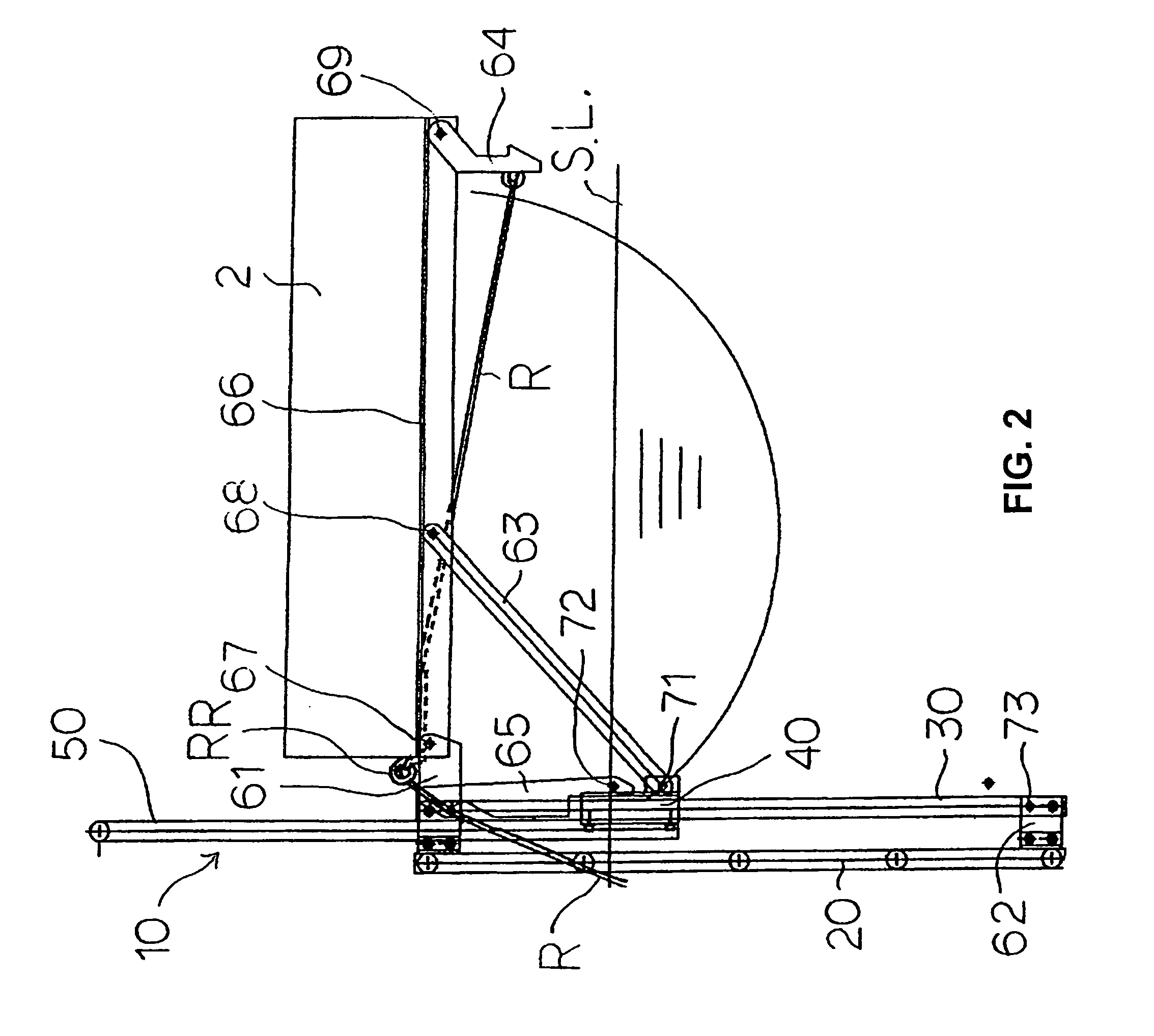
[0034] Preferred embodiments of the marine safety ladder according to the present utility model will now be described in detail on a floating pier with reference to the accompanying drawings. The component with the reference numeral 10 in FIGS. 1, 2, 4, 5, and 6 is a floating pier safety ladder. The floating pier safety ladder 10 includes a main ladder 20, guide rails 30, a sliding member 40, an auxiliary ladder 50, and various other ladder constituting parts that will be described below.

[0035] The main ladder 20 is comprised of beams 21, which are two straight parts disposed in parallel, and rungs 22, which are provided at a plurality of locations spaced a suitable distance apart in the lengthwise direction of the beams 21 and bridging the beams 21. The main ladder 20 is not limited to the structure shown in the drawings, and the beams 21 can be U-shaped at the bottom ends, the top ends, or both ends, as with the beams 51 of the auxiliary ladder 50 described below. Also, for examp...


PUM


Abstract

To provide a marine safety ladder that makes rescue possible within a short time, without posing any risk of contact with a pleasure boat or the like, without causing any additional concern in the operation of boats during docking and departure, without the risk of injury to a person who has fallen, etc., and without the risk of falling when the ladder is being stowed. A top hinge member (67) is connected and fixed to one end, a middle hinge member (68) is connected and fixed to the middle, and a bottom hinge member (69) is connected and fixed to the other end, respectively, to, in the width direction, the underside of a deck (2) of a floating pier (1) or of a transom step (2′) of a boat (1′); and a main ladder (20) and guide rails (30) are provided rotatable about the top hinge member (67) via top connecting members (61); and with a bottom latch element (64) being engaged with the bottom end of the main ladder (20) or members in the vicinity thereof, a sliding member (40) is located at the bottom end of the guide rails (30), and all constituting parts are stowed within the width of the deck (2) of the floating pier (1).

Description

FIELD OF TECHNOLOGY [0001] The present utility model relates to a safety ladder that is provided to a floating pier used for pleasure boats and the like and installed in a marina or the like or that is provided to a pleasure boat. BACKGROUND ART [0002] A person waling on the deck of a floating pier installed in a marina or the like and used for pleasure boats and so forth, or people on board a pleasure boat or the like that is moored or preparing to dock or depart, sometimes accidentally fall into water. The marine safety ladders that reach from the deck to the water are provided along the floating pier in case such accidents should happen. The person who has fallen into the water or a rescuer who has gone into the water to help the fallen person makes his or her way to the safety ladder, climbs the safety ladder, and comes out of the water onto the deck of the floating pier. Similar accidents would occur on pleasure boats when people fall off the transom step. [0003] A rescue appar...

Claims


Application Information

Patent Timeline
IPC IPC(8): B63B17/00
CPCB63B27/146
Inventor NAKANO, YUKINARI
Owner MARINE WORKS
Learn More