Coating film transfer tool

a technology of coating film and transfer tool, which is applied in the direction of paper hanging, combustion air/fuel air treatment, and erasing devices, etc., can solve the problems of burdensome work for users, coating film cannot be transferred thereto, and the coating film transfer tool does not achieve the construction to bring a great deal, so as to achieve the effect of reducing sag

Inactive Publication Date: 2007-05-24
PLUS STATIONARY CORP
View PDF7 Cites 15 Cited by
  • Summary
  • Abstract
  • Description
  • Claims
  • Application Information

AI Technical Summary

Benefits of technology

[0009] The present invention has been made with a view toward the above-mentioned problems, and therefore it is an object of the present invention to provide a coating film transfer tool capable of eliminating a sag when being used, while protecting a transfer tape when not being used.
[0019] and is characterized in that, when a sliding operation to accommodate the transfer head is performed by the slide mechanism, the slide mechanism is engaged with the supply reel, and rotates the supply reel reversely, and thereby the following effect is obtained, that is, capable of eliminating the sag when being used, while protecting the transfer tape by the slide mechanism when not being used.

Problems solved by technology

In the coating film transfer tool as described above, when the transfer tape sags without being tensioned on a transfer head, the transfer tape cannot be appropriately pressed against a transfer target, so the coating film cannot be transferred thereto.
However, it has been burdensome work for a user, every time the sag occurs in the transfer tape, to rotate the supply reel, the take-up reel, the rotating member directly coupled thereto, or the like to wind up the transfer tape.
However, such a coating film transfer tool does not achieve a construction to bring a great deal of effect for eliminating the sag of the transfer tape.

Method used


Image

  • Coating film transfer tool
  • Coating film transfer tool
  • Coating film transfer tool

Examples


Embodiment Construction

[0032] A description will be made below in detail of a coating film transfer tool according to the present invention with reference to the drawings while mentioning a preferred embodiment. (Summary of Entire Construction)

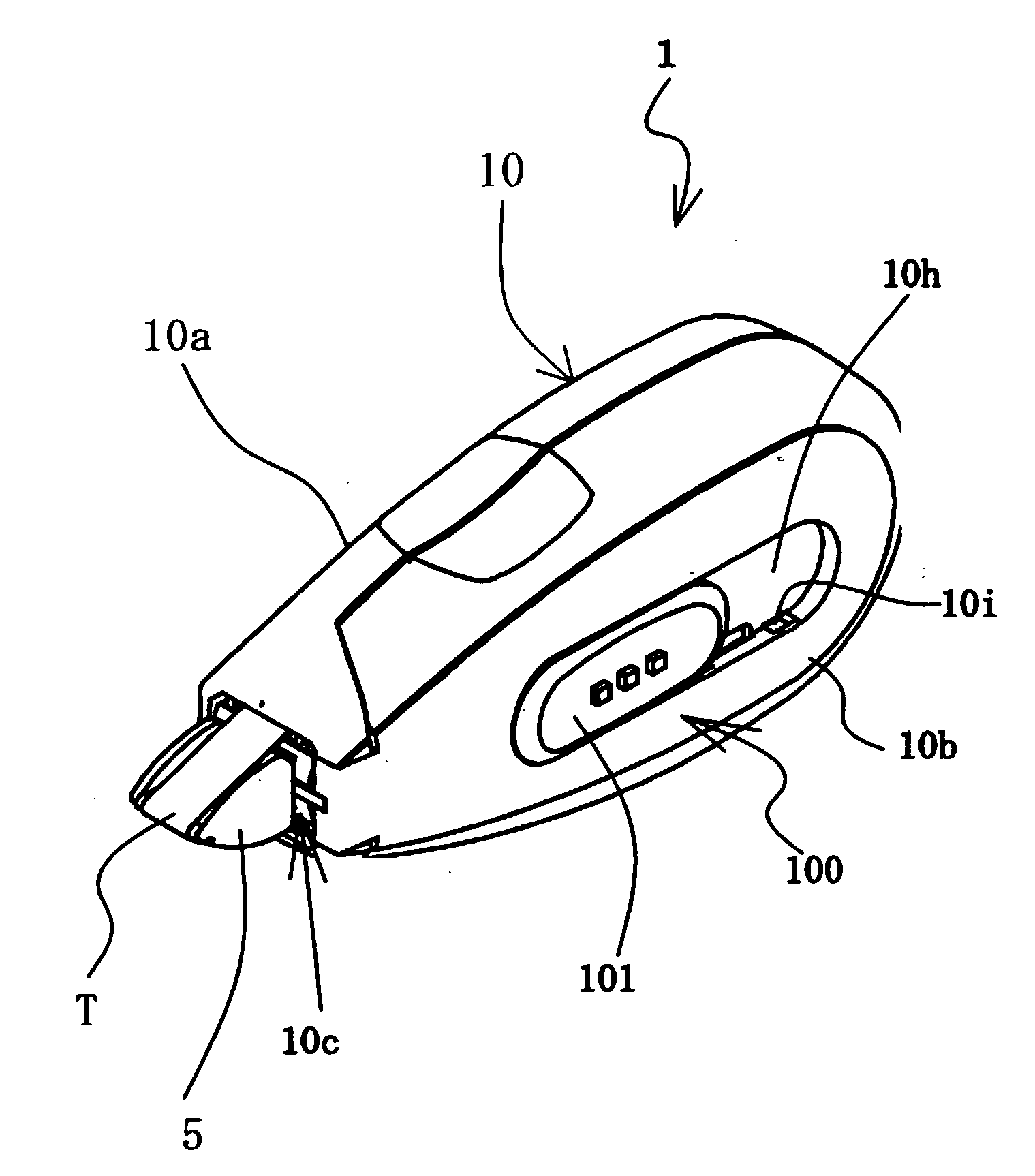
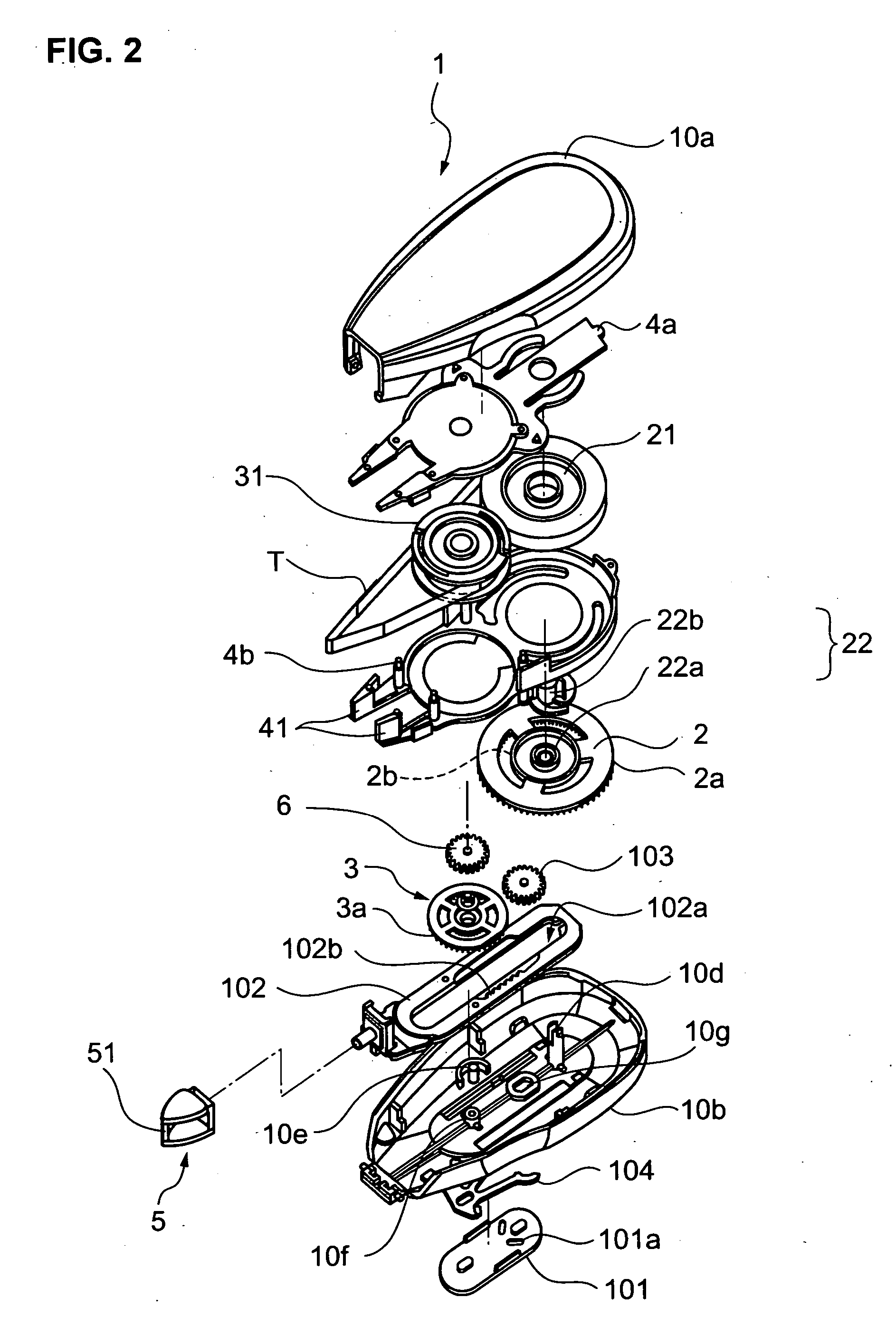
[0033]FIG. 1 is a perspective view showing an exterior of a construction of the coating film transfer tool according to an embodiment of the present invention. As shown in FIG. 1, a case upper portion 10a and a case lower portion 10b which function as a case 10 of a coating film transfer tool 1 of this embodiment are formed so as to be capable of being assembled with each other. A tape unit 4 is built in an inside of the case 10. The tape unit 4 is structured by winding a transfer tape T in which a transfer layer formed of a paste or the like is provided on a surface of a feeding tape. The feeding tape functions as a medium for feeding the transfer layer.

[0034] The coating film transfer tool according to the present invention comprises a transfer head 5 which tens...


PUM

PropertyMeasurementUnit
tensionaaaaaaaaaa
transparentaaaaaaaaaa
tensionsaaaaaaaaaa

Abstract

Provided is a coating film transfer tool capable of eliminating a sag when being used, while protecting the transfer tape when not being used. The coating film transfer tool includes: a slide mechanism which causes the transfer head to slide allowing the transfer head to contact with the transfer tape and to protrude from the case in order to perform the transfer, and / or accommodate the transfer head into the case; and a slip mechanism which, when a sliding operation to cause the transfer head to protrude is performed by the slide mechanism, releases interlocking between the supply bobbin and the supply reel, and, when the supply bobbin rotates in the direction of winding up the transfer tape by running of the transfer tape at a time of the transfer, rotates the supply reel and the supply bobbin in interlocking with each other, the slip mechanism being interposed between the supply bobbin and the supply reel, in which, when a sliding operation to accommodate the transfer head is performed by the slide mechanism, the slide mechanism is engaged with the supply reel, and rotates the supply reel reversely.

Description

BACKGROUND OF THE INVENTION [0001] 1. Field of the Invention [0002] The present invention relates to a construction of a coating film transfer tool for use in applying a paste and correcting a literal error, the coating film transfer tool being structured by winding a transfer tape having a paste provided on a surface of a resin tape or a paper tape around a supply bobbin. [0003] 2. Description of the Related Art [0004] Heretofore, a coating film transfer tool for use in applying a paste and correcting a literal error has been proposed. As a construction of such a coating film transfer tool, there is generally known a construction which includes: a supply reel onto which a supply bobbin having an unused transfer tape wound around the supply bobbin is attached; a take-up reel onto which a take-up bobbin having the transfer tape used after being drawn out of the supply bobbin wound around the take-up bobbin is attached; and reel interlocking means for interlocking the supply reel and ...

Claims


Application Information

Patent Timeline
Patent Type & Authority Applications(United States)
IPC IPC(8): B43L19/00B44C7/00
CPCB43L19/0068B65H37/007Y10T156/1795Y10T156/1348Y10T156/18F02B51/04F02B51/06F02M27/045F02M27/06
Inventor USHIJIMA, JUN
Owner PLUS STATIONARY CORP
Why Eureka
Try Eureka