Well production by fluid lifting

a technology of fluid lifting and wells, which is applied in the direction of fluid removal, earth-moving drilling, borehole/well accessories, etc., can solve the problem of limited tubing down-flow capacity

Inactive Publication Date: 2007-05-24
DANIELS VERNON DALE +1
View PDF8 Cites 12 Cited by
  • Summary
  • Abstract
  • Description
  • Claims
  • Application Information

AI Technical Summary

Benefits of technology

[0014] These and other objects of the invention are accomplished by one preferred embodiment in which a pre-positioned production tube is wire-line or slick-line perforated at a point above the production zone packer and, preferably, below or proximate of an oil-w...

Problems solved by technology

However, the tubing do...

Method used


Image

  • Well production by fluid lifting
  • Well production by fluid lifting
  • Well production by fluid lifting

Examples


first embodiment

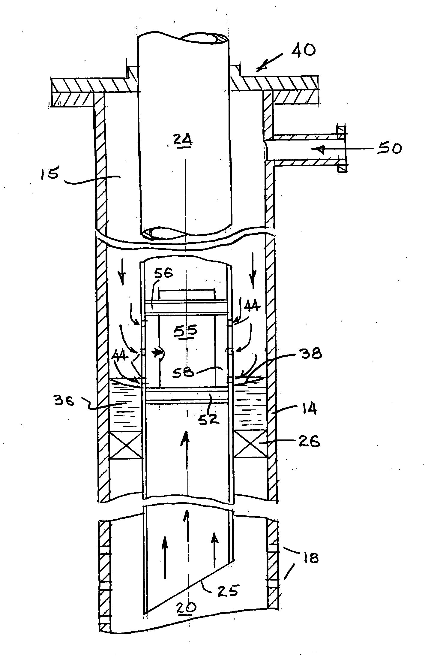
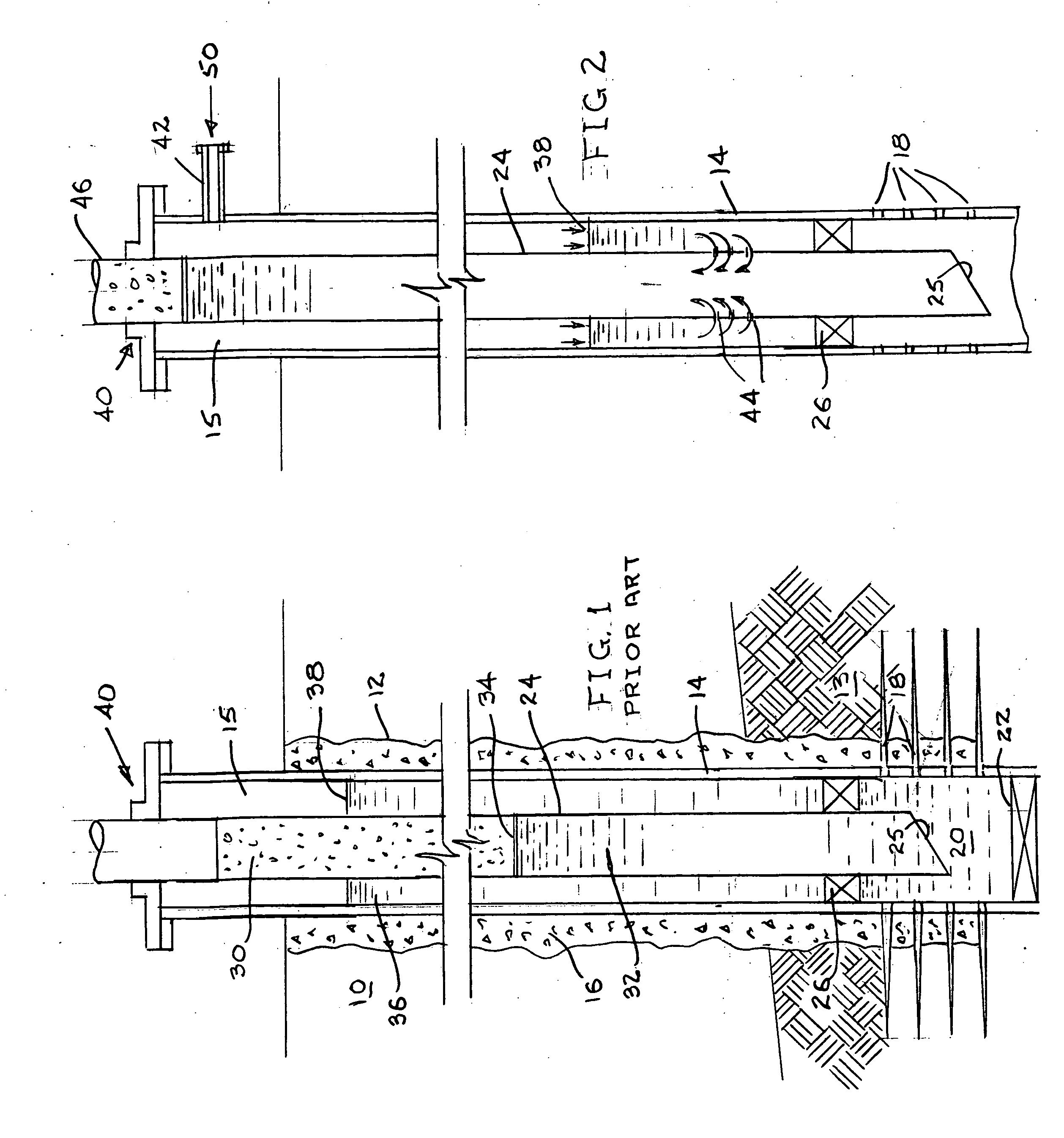
[0036] In the invention, represented by FIG. 2, for example, restoration of productive flow from a “depleted” well includes the preparatory step of securing an injection flow connection 42 proximate of the wellhead 40 for injecting pressurized charging fluid into the casing annulus 15. The charging fluid is preferably oxygen depleted air such as non-cryogenic nitrogen. However, other non oxidizing fluids such as natural gas, methane, carbon dioxide may also be suitable depending on the well site economics.

[0037] Further to the charging fluid connection, 42, the preexisting production tube 24 is in situ perforated at a strategic point 44 above the packer 26. Usually, in situ production tube perforations are executed by a “slick line” or wire-line operation that includes a small diameter perforating gun suspended from the surface at the end of a wire-line. The depth of tubing perforation is selected to sufficiently reduce the tubing column overburden pressure sufficient to restore pro...

third embodiment

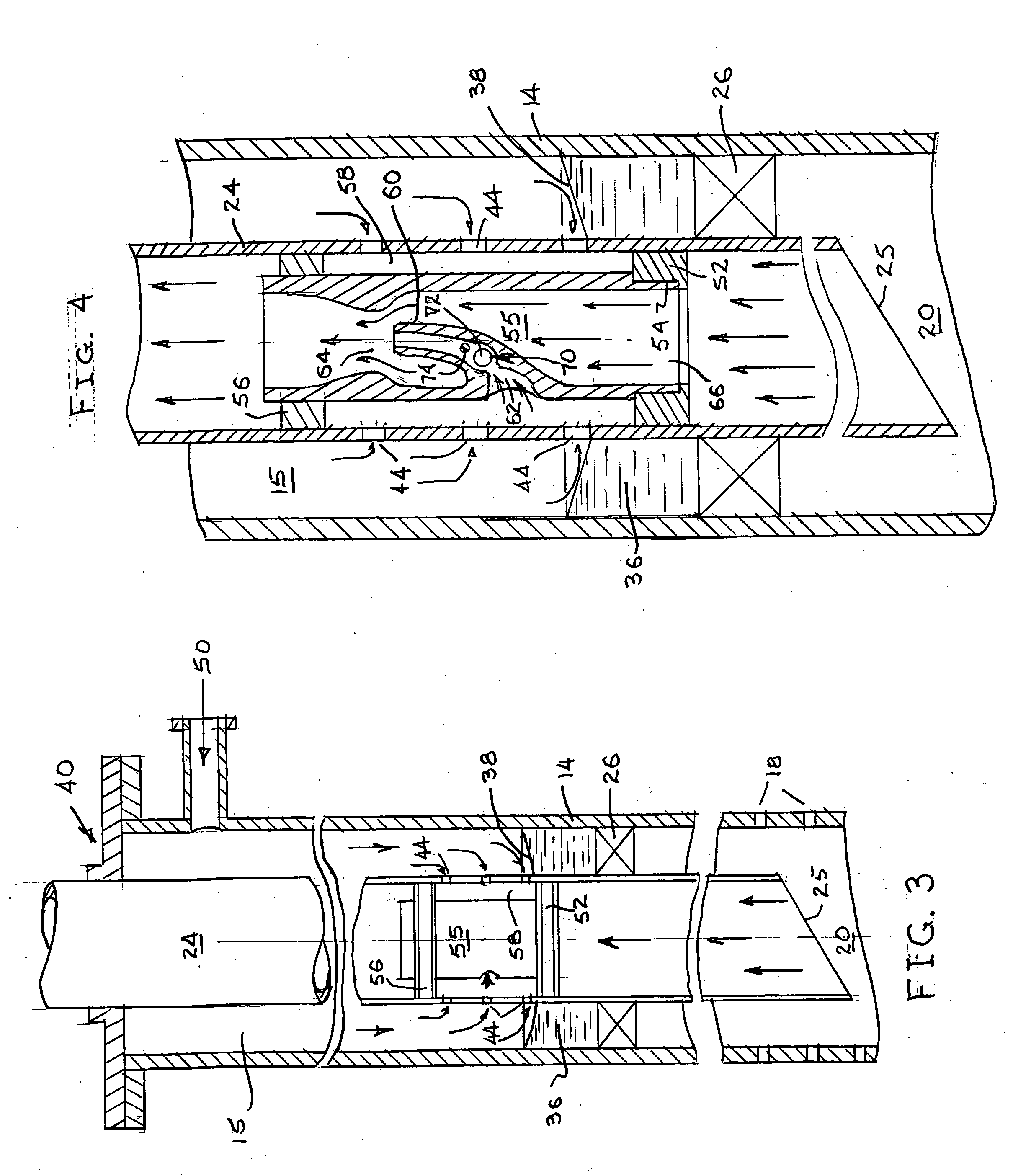
[0048]FIGS. 5 and 6 illustrate the invention that comprises a jet pump sub 80 that is line coupled in a straight tubing string 24 or below a side pocket mandrel tube 82.

[0049] The jet pump sub 80 essentially conforms to the jet pump body 55 illustrated by FIG. 4 with the exception that the nozzle inlet 62 is protected by a slotted screen 84, for example.

[0050] Unless the original production tube is installed with the jet pump sub 80 in-line, which it may be, it will be necessary to withdraw the tubing 24 to insert the pump sub 80. However, no wire-line or perforating procedures are necessary. The entire casing annulus becomes the charging fluid plenum for the pump sub 80.

[0051] In the case of the FIG. 6 embodiment, a gas-lift valve string 28 comprises several lift valves 90, 92 and 94, for example. The valve orifices and mechanisms are disposed in side-pocket mandrel joints 82 above the jet pump 80.

[0052] Operatively, the casing annulus 15 is charged with an opening pressure that...


PUM


Abstract

Oil production from formerly producing wells may be restored without removing a preexisting production tube by perforating the production tube above the tubing packer and charging the casing annulus at the surface with a pressurized charging fluid fluid, preferably deoxygenated air, that is lighter than water. The pressurized charging of the casing annulus with charging fluid is continued to purge the production tube flow bore of a static water column and reduce the tubing column head pressure against the formation production zone.

Description

BACKGROUND OF THE INVENTION [0001] 1. Field of the Invention [0002] The present invention relates to methods and apparatus for enhancing the extractive flow of crude petroleum from production wells. [0003] 2. Description of Related Art [0004] When a petroleum extraction well is first completed, in situ formation pressure is often sufficient to drive the formation fluid (crude oil) to the surface. Over time, with the continued extraction of the in situ fluid, the original formation pressure declines to the point of insufficient internal energy to drive a flow of fluid to the surface. This circumstance is exacerbated by the frequent invasion of water and other contaminating fluids into the formation interstices vacated by the original formation fluid. These contaminating fluids ultimately find their way into the production flow stream and into the well production tube. Due to a greater specific gravity of water than oil, the well production tube slowly fills with water to prevent all ...

Claims


Application Information

Patent Timeline
IPC IPC(8): E21B43/00
CPCE21B43/122
Inventor DANIELS, VERNON DALEDANIELS, DANNY KENT
Owner DANIELS VERNON DALE
Why Eureka
Try Eureka