
Wire pulling device

a wire pulling device and wire technology, applied in the direction of cables laying apparatus, hoisting equipment, transportation and packaging, etc., can solve the problems of time-consuming and laborious, difficult and time-consuming wire pulling through such long runs, and increase the risk of injury, so as to achieve efficient and quick wire pulling. , the effect of sufficient torque and speed

Inactive Publication Date: 2007-05-24
WIRE PRO USA
View PDF18 Cites 19 Cited by
  • Summary
  • Abstract
  • Description
  • Claims
  • Application Information

AI Technical Summary

Benefits of technology

[0013] The present invention is a portable wire pulling device that utilizes the rotational power and control functions of a cordless, battery-operated electric hand drill to selectively drive a rotatable reel of the portable wire pulling device with sufficient torque and speed to efficiently and quickly pull a wire thereby.
[0020] The folding frame of the present wire pulling device may be used to brace the top of the wire pulling device against any convenient overhead building member to provide stability during the pulling of the wire. A rope guide is also preferably incorporated into the wire pulling device to allow the rope to be wound uniformly onto the reel spool. Its light-weight and portability allow the present wire pulling device to be safely placed and used while working on a high lift or scaffold.
[0021] The present invention provides a light-weight, portable, efficient, fast and easy to operate device that can pull wire over large distances in a fraction of the time required for conventional wire pulling. This greatly reduces the man hours and related costs usually required to properly perform this operation.

Problems solved by technology

Some wire runs can exceed 1000 feet in length and it becomes very difficult and time consuming to pull wires through such long runs.
As such, this process is time consuming and expensive in man hours.
Safety may also become an issue because workers are often required to perform this difficult operation while working high on scaffold or on a lift.
However, all of these prior art wire pulling devices suffer from various deficiencies.
For instance, these prior art wire pulling devices are not too portable given their size and bulk.
Moreover, since these prior art wire pulling devices require use of alternating current machinery for motive power they are restricted for use in places where there is a source of alternating current for operation.
Furthermore, these prior art wire pulling devices do not provide flexibility in positioning for wire pulling, wire pulling capabilities or other constraints.

Method used


Image

  • Wire pulling device
  • Wire pulling device
  • Wire pulling device

Examples


Embodiment Construction

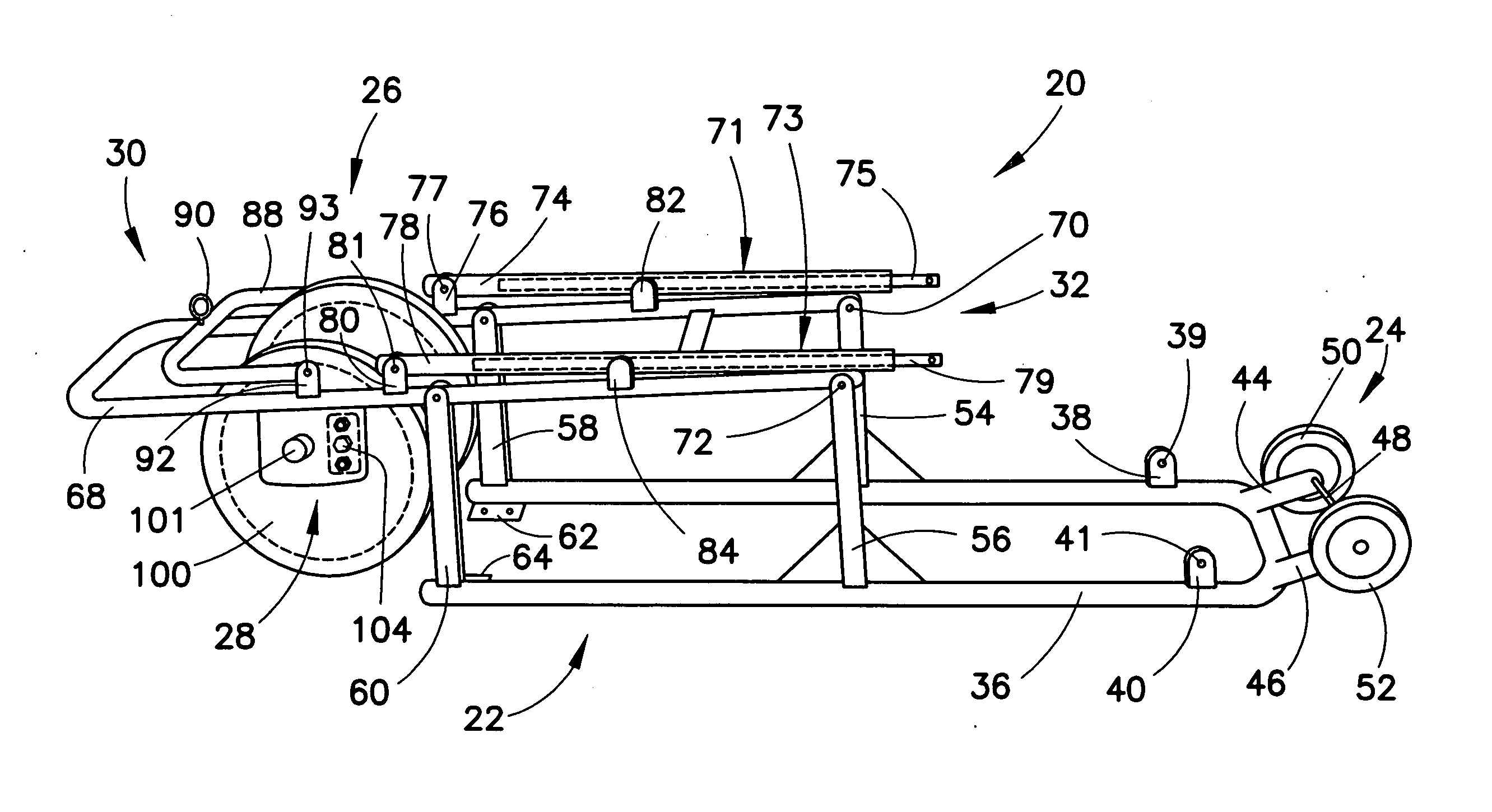
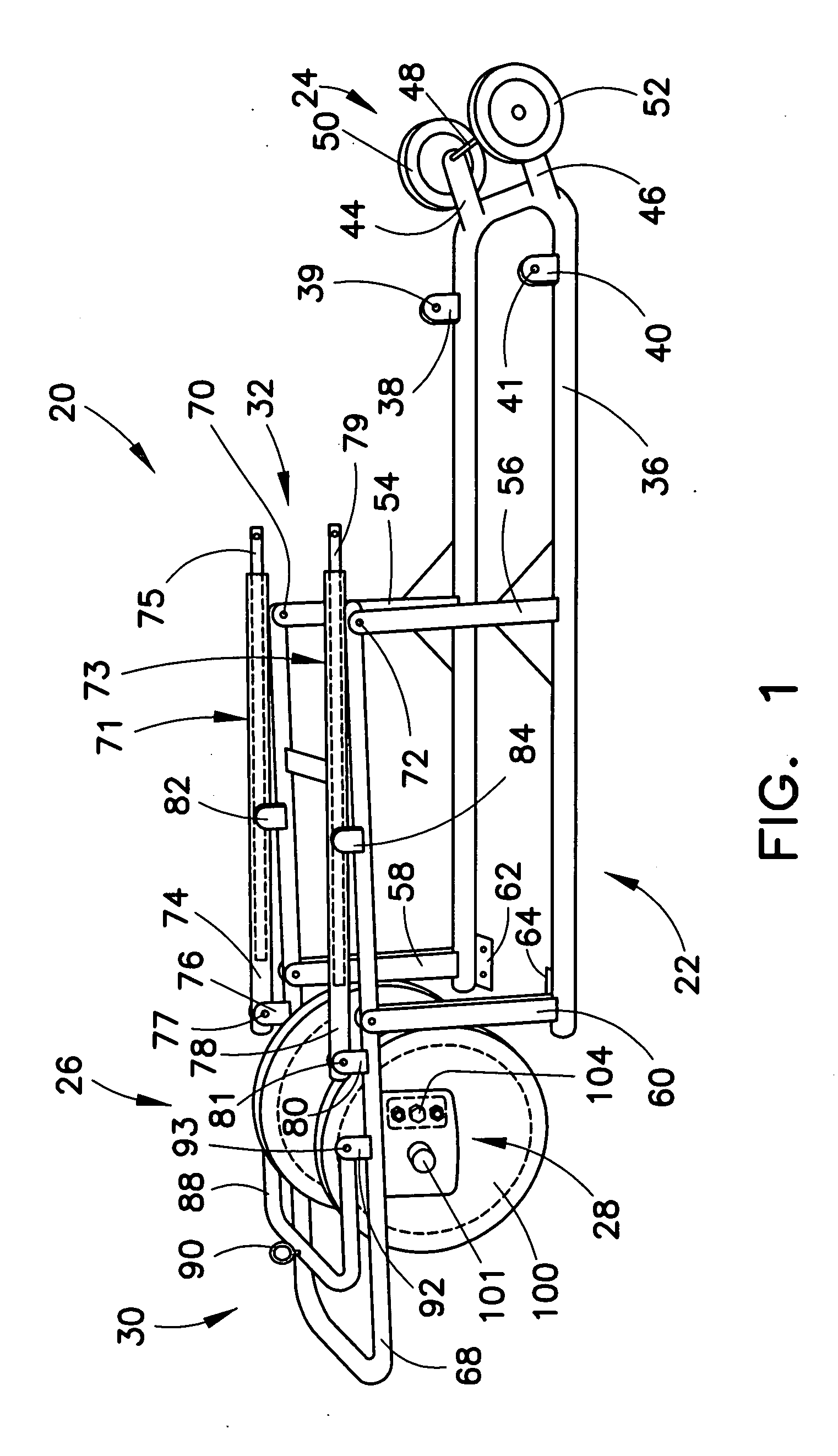
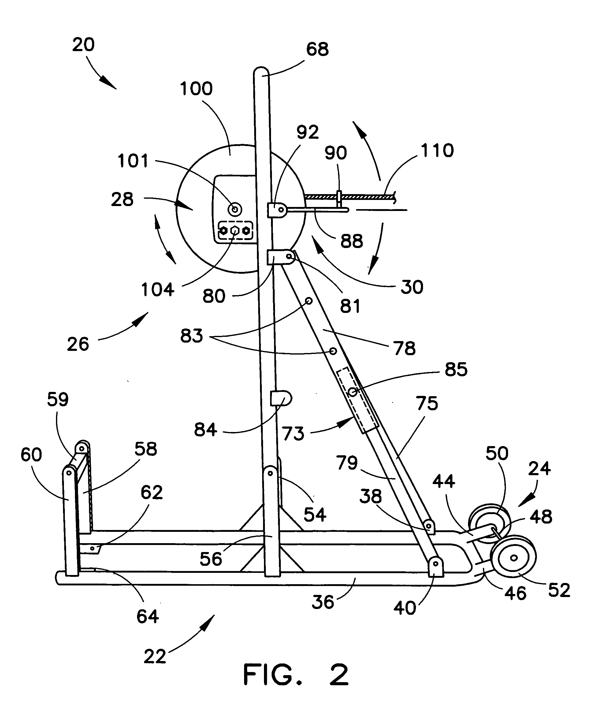
[0033] Referring to FIGS. 1-8, and particularly FIG. 1, there is depicted an exemplary embodiment of a portable wire pulling device, generally designated 20, fashioned in accordance with the principles presented herein. The wire pulling device 20 is formed in general by a frame assembly or frame 22, a wheel assembly 24 attached to the frame assembly 22, a spool or reel assembly 26 attached to the frame assembly 22, a drive assembly 28 that is operatively coupled with the reel assembly 24 and a pivoting rope guide assembly 30. The wire pulling device 20 is shown in a folded, collapsed or stowed position. FIGS. 2 and 3 depict the wire pulling device 20 in other positions. Particularly, FIG. 2 depicts the wire pulling device 20 in an upright position, while FIG. 3 depicts the wire pulling device 20 in an angled position. FIG. 4 illustrates that the wire pulling device 20 is portable through use of its wheel assembly 24 particularly when in an angled position such as depicted in FIG. 3....


PUM


Abstract

The present invention is a portable wire pulling device that receives and utilizes the rotational power and control features and functions of a cordless, battery-operated electric hand drill to selectively drive a rotatable reel of the portable wire pulling device with sufficient torque and speed to efficiently and quickly pull a wire thereby. The wire pulling device has a frame configured to rotatably carry and selectively position a take-up reel, and a drive interface coupled to the reel and having an input drive shaft configured to receive the hand drill for applying rotational power to the drive mechanism to rotate the reel. No on-site power is needed. The frame extends from a folded position into an upright position and into an angled position in order to pull wire for different applications.

Description

RELATED APPLICATION [0001] This patent application claims the benefit of and / or priority to U.S. Provisional Patent Application No. 60 / 733,854 filed Nov. 7, 2005, entitled “Wire Pulling Device” the entire contents of which is specifically incorporated herein by reference.BACKGROUND OF THE INVENTION [0002] 1. Field of the Invention [0003] The present invention relates to portable wire, cable and line pulling devices. [0004] 2. Background Information [0005] Larger and larger commercial buildings, warehouses, and other super sized structures are now being constructed that require long runs of electrical wires, cables, lines and / or the like (collectively, wires) during construction. Some wire runs can exceed 1000 feet in length and it becomes very difficult and time consuming to pull wires through such long runs. Traditionally, a rope is threaded through the space where the wire is to be run with one end of the rope fastened onto a specific wire or wire bundle. It is the electrician's j...

Claims


Application Information

Patent Timeline
Patent Type & Authority Applications(United States)
IPC IPC(8): H02G1/08
CPCB65H75/305B65H75/403H02G1/08H02G1/085H02G11/02
Inventor BAUGHMAN, JAMES E.O'TOOLE, DANIEL S.
Owner WIRE PRO USA
Learn More