
Image processing method and apparatus for color enhancement and correction

Inactive Publication Date: 2007-05-24
BEYOND INNOVATION TECH
View PDF5 Cites 8 Cited by
  • Summary
  • Abstract
  • Description
  • Claims
  • Application Information

AI Technical Summary

Benefits of technology

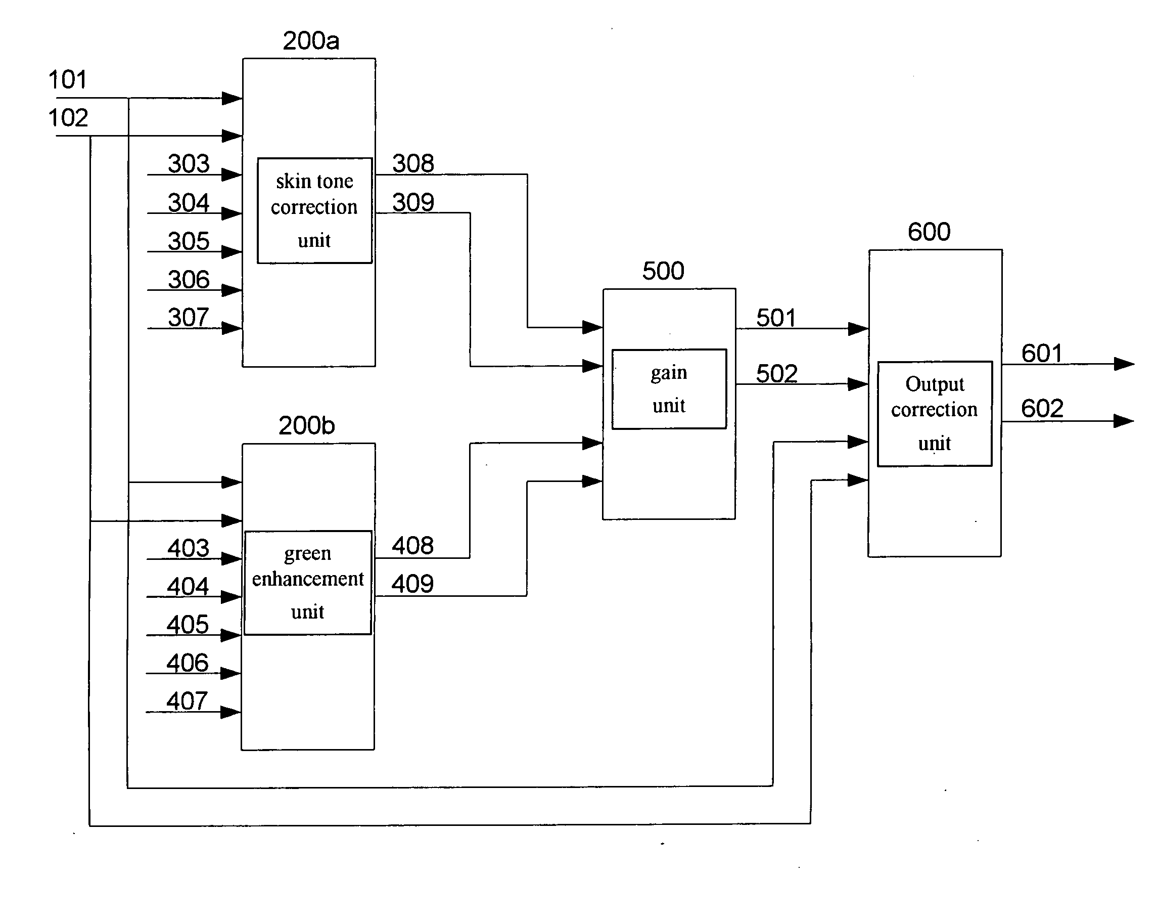
[0009] Another object of the present invention is to provide an image processing method and apparatus to make change of the value of each pixel of the digital color image in sequence in operational processing so as to get the smoothest effect in color correction and enhancement.
[0010] Another object of the present invention is to provide an image processing method and apparatus for color correction and enhancement utilizing the calculation algorithm, GAIN *{2n−[Y−X*tan(θ)]} when {2n−[Y−X*tan(θ)]}>0, to make change of the value of each pixel of the digital color image in sequence in color correction and enhancement processing so as to get the smoothest effect.

Problems solved by technology

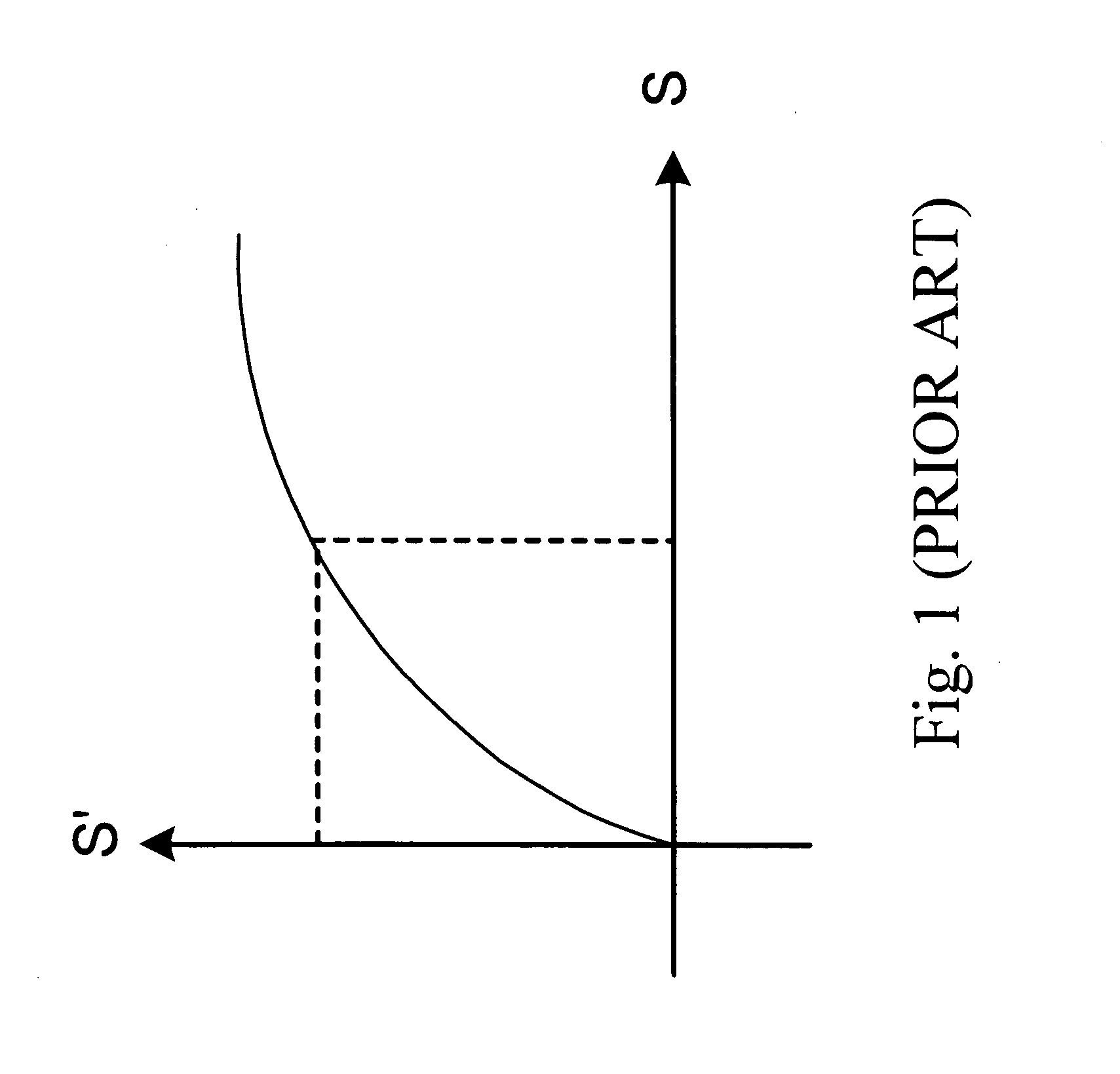
Hence the difficulty and problem associated with conventional image processing techniques utilizing the color look up table (CLUT) method is that sufficient memory is necessary for storing the color look-up table (CLUT).
It will waste a lot of memories.
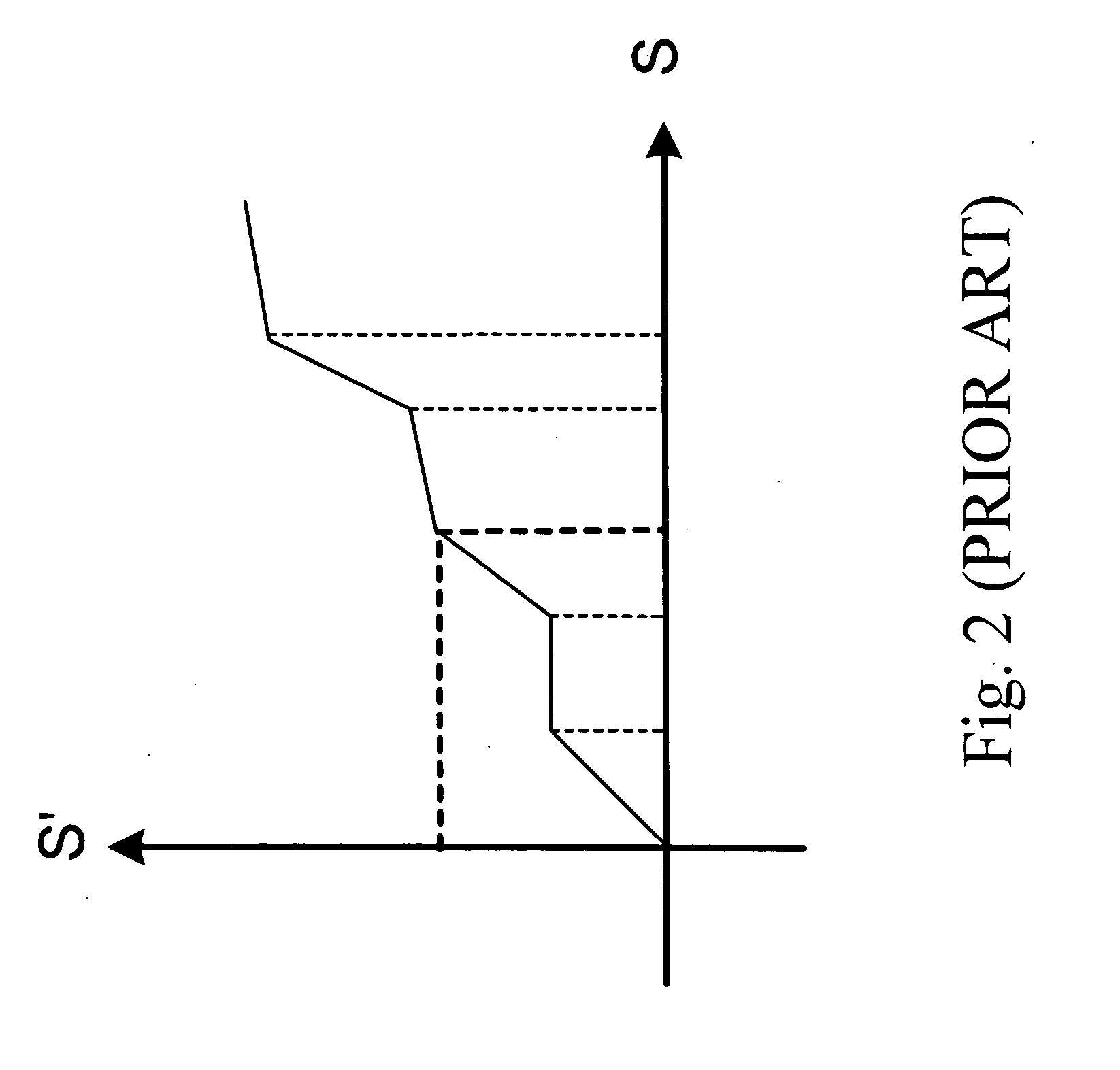
Although the color enhancement and correction of a digital image data in the piecewise linear approximation method provides a desired effect on the digital image data, it may cause an undesired side effect thereon.

Method used


Image

  • Image processing method and apparatus for color enhancement and correction
  • Image processing method and apparatus for color enhancement and correction
  • Image processing method and apparatus for color enhancement and correction

Examples


Embodiment Construction

[0031] In the following detailed description of the present invention, numerous specific details are set forth in order to provide a thorough understanding of the present invention. However, it will be obvious to one skilled in the art that the present invention may be practiced without these specific details. In other instances well known methods, procedures, components, and circuits have not been described in detail so as not to unnecessarily obscure aspects of the present invention.

[0032] Referring to FIG. 3 of the drawings, a chromaticity diagram of the color space according to a preferred embodiment of the present invention is illustrated. Note that in describing different video formats, the YUV video format is frequently mentioned and used throughout the specification. It is common knowledge that YUV is a video color model in which luminance information (Y) is separated from chrominance information (U and V). Such YUV video components are often written in a variety of ways: (...


PUM


Abstract

The present invention provides an image processing method for color correction. The image processing method for color correction comprises the steps of: (a) determining an angle on a color space according to an image data of a basic color, (b) determining a first straight line on the color space according to the angle, wherein the first straight line makes the same angle with the color space, (c) determining a second straight line on the color space according to an image data of a pixel and the angle, wherein the slope of the second straight line is the same to that of the first straight line, (d) providing a processing range parameter and according to the processing range parameter, determining a third straight line and a fourth straight line of two color correction range lines which are parallel to the first straight line, wherein the first straight line is a center line between the third straight line and the fourth straight line, (e) determining at least one another color correction range bounded line according to the processing range parameter and dividing several regions among the color correction range bounded line, the third straight line, and the fourth straight line, wherein every region respectively corresponds to a correction value, (f) determining the color intensity difference value according to the correction value corresponding to the region on which the image data of the pixel is located, and (g) correcting the image data of the pixel according to the color intensity difference value.

Description

BACKGROUND OF THE PRESENT INVENTION [0001] 1. Field of Invention [0002] The present invention relates to an image processing method and apparatus utilizing a design of a hardware circuit or a program to execute color enhancement and correction, and more particularly to an image processing method and apparatus utilizing a chromaticity diagram in different color space to process digital color image data for color enhancement and correction. [0003] 2. Description of Related Arts [0004] There are a variety of conventional image processing techniques for processing color enhancement and correction of digital color image data. In conventional image processing, many color scales, so called “color spaces,” are used in various conventional image processing techniques to process color enhancement and correction of digital color image data. However, a variety of conventional image processing techniques usually utilize an independent color space to convey color values in numerical terms. In oth...

Claims


Application Information

Patent Timeline
IPC IPC(8): G03F3/08
CPCH04N1/6058H04N1/62H04N1/628
Inventor SHEN, CHUNG-LIHSU, YU-SHAN
Owner BEYOND INNOVATION TECH
Learn More