
Optical transmission system and optical filter assembly for submarine applications

a technology of optical transmission system and optical filter assembly, which is applied in the direction of fibre transmission, electrical apparatus, laser details, etc., can solve the problems of high pump power required to reach higher output power levels, limited power levels of optical amplifier assemblies, and induced insertion loss due to prior art optical amplifier assemblies. , to achieve the effect of high output power

Active Publication Date: 2007-05-24
RPX CORP
View PDF9 Cites 9 Cited by
  • Summary
  • Abstract
  • Description
  • Claims
  • Application Information

AI Technical Summary

Benefits of technology

[0009] It is the object of the present invention to provide an optical amplifier assembly for submarine applications which provides high output power while obviating the above-mentioned disadvantages without suffering from NF degradation.
[0010] It is further an object of the present invention to provide an optical transmission system for submarine applications, which operates at high span losses and wide bandwidth without suffering from excessive overall system costs.
[0013] As a general idea, the present invention proposes to use a double stage fibre amplifier architecture with a GFF inserted between the two amplifier stages. This particular approach further enables a variety of pump power splitting schemes between the two amplifier stages in order to guarantee a submarine reliability of the overall system by providing a possibility of optimising pump power injection between the first and second amplifier stages in order to achieve various gain and output power characteristics.
[0014] In an embodiment of the optical amplifier assembly in accordance with the present invention the common pump source comprises a number of pump field combiners in operative connection with the coupler adapted to multiplex the plurality of pump light sources. Preferably, the pump light sources are devised as laser diodes and the pump field combiners are devised as polarisation beam combiners (PBC). In this way, a large number of individual pump light sources can effectively be coupled to the amplifier stages thus increasing the reliability of the overall system, which is an important feature for submarine applications. In addition, use of polarisation beam combiners effectively reduces polarisation dependent gain (PDG) in the optical transmission system.
[0015] In further embodiments of the optical amplifier assembly in accordance with the present invention the coupler is a star coupler adapted to inject the same pump power into the first and second fibre amplifiers of the first and second double stage fibre amplifiers. In this way, a pump power splitting ratio of 50:50 can be implemented.
[0016] In order to be able to vary a pump power input to the first and second stages of the double stage fibre amplifiers, in another embodiment of the optical amplifier assembly in accordance with the present invention the pump source is coupled via said coupler to a first and a second splitter having a predefined splitting ratio, wherein the first splitter couples pump light at said predefined splitting ratio into the first and second fibre amplifiers of the first double stage fibre amplifier and the second splitter couples pump light at said predefined splitting ratio into the first and second fibre amplifiers of the second double stage fibre amplifier. Alternatively, the first and second splitters could have different splitting ratios, hereinafter also referred to as “pump power splitting ratios”. However, as submarine systems are usually purely symmetrical, normally equal splitting ratios for the East West direction and the West East direction are used. In a preferred further embodiment of the optical amplifier assembly in accordance with the present invention the said couplers are devised in the form of fused fibre couplers. In this way, various pump power splitting ratios can be easily realised.

Problems solved by technology

If high gain (>16 dB) and wide transmission bandwidth (27 nm or more) are considered, the induced insertion loss due to prior art optical amplifier assemblies becomes extremely large.
Thus, in the prior art, the output power of optical amplifier assemblies, i.e. of the individual double stage fibre amplifiers comprised therein, is limited to only moderate power levels.
Alternatively, pump power required to reach higher output power levels becomes extremely high, such that an excessively large number of pump light sources, e.g. laser diodes, has to be employed which leads to a reduced cost-effectiveness of the overall system.
As a result to these system modifications, induced losses of the GFF will increase drastically.
However, for the reasons indicated above, it will not be possible to increase the output power of prior art optical amplifier assemblies accordingly.
However, if the output power of amplifiers used in optical transmission systems is too low, the overall system performance can only be increased to an acceptable level by adding additional amplifiers to the system in order to reduce span loss.
Such an approach, however, will lead to an increase in overall system costs.
On the other hand, increasing the output power by providing powerful pump light sources suffers from the fact, that pump power higher than 500 mW is not available.
Simply providing an ever increasing number of individual pump light sources will again have a negative effect on overall system cost.

Method used


Image

  • Optical transmission system and optical filter assembly for submarine applications
  • Optical transmission system and optical filter assembly for submarine applications
  • Optical transmission system and optical filter assembly for submarine applications

Examples


first embodiment

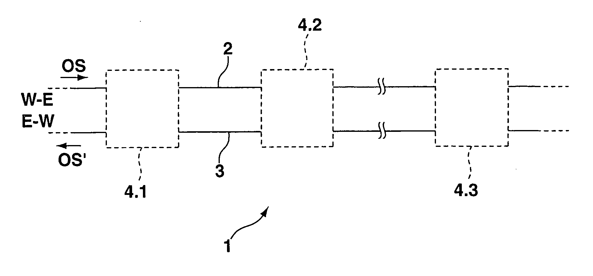
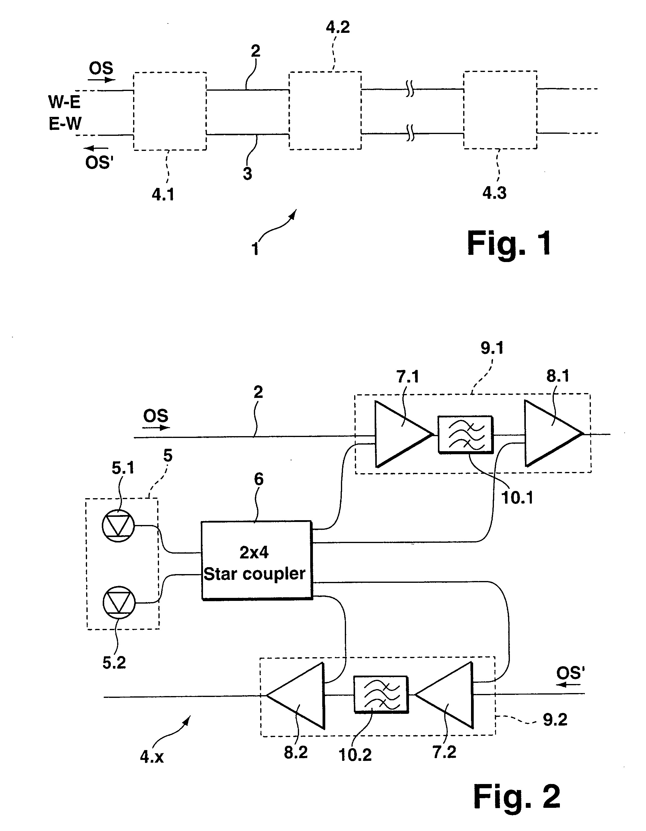
[0030]FIG. 2 shows a block diagram of the optical amplifier assembly in accordance with the present invention. In order to comply with the above-described illustration in FIG. 1, the optical amplifier assembly of FIG. 2 has been assigned reference numeral 4.x, wherein reference numeral 4.x replaces reference numerals 4.1-4.3 of FIG. 1 in a generic way.

[0031] The optical amplifier assembly 4.x of FIG. 2 comprises two pump light sources 5.1, 5.2, e.g. laser diodes, which effectively form a common pump source 5 as indicated by a dashed box in FIG. 2. The pump light sources 5.1, 5.2 are operably connected with a star coupler 6, which couples the common pump source 5, i.e. the individual pump light sources 5.1, 5.2 to respective first 7.1, 7.2 and second fibre amplifiers 8.1, 8.2 arranged on the first optical fibre 2 and on the second optical fibre 3, respectively, for amplifying the optical signals OS, OS' propagated thereon. As depicted in FIG. 2, the first fibre amplifier 7.1 and the ...

second embodiment

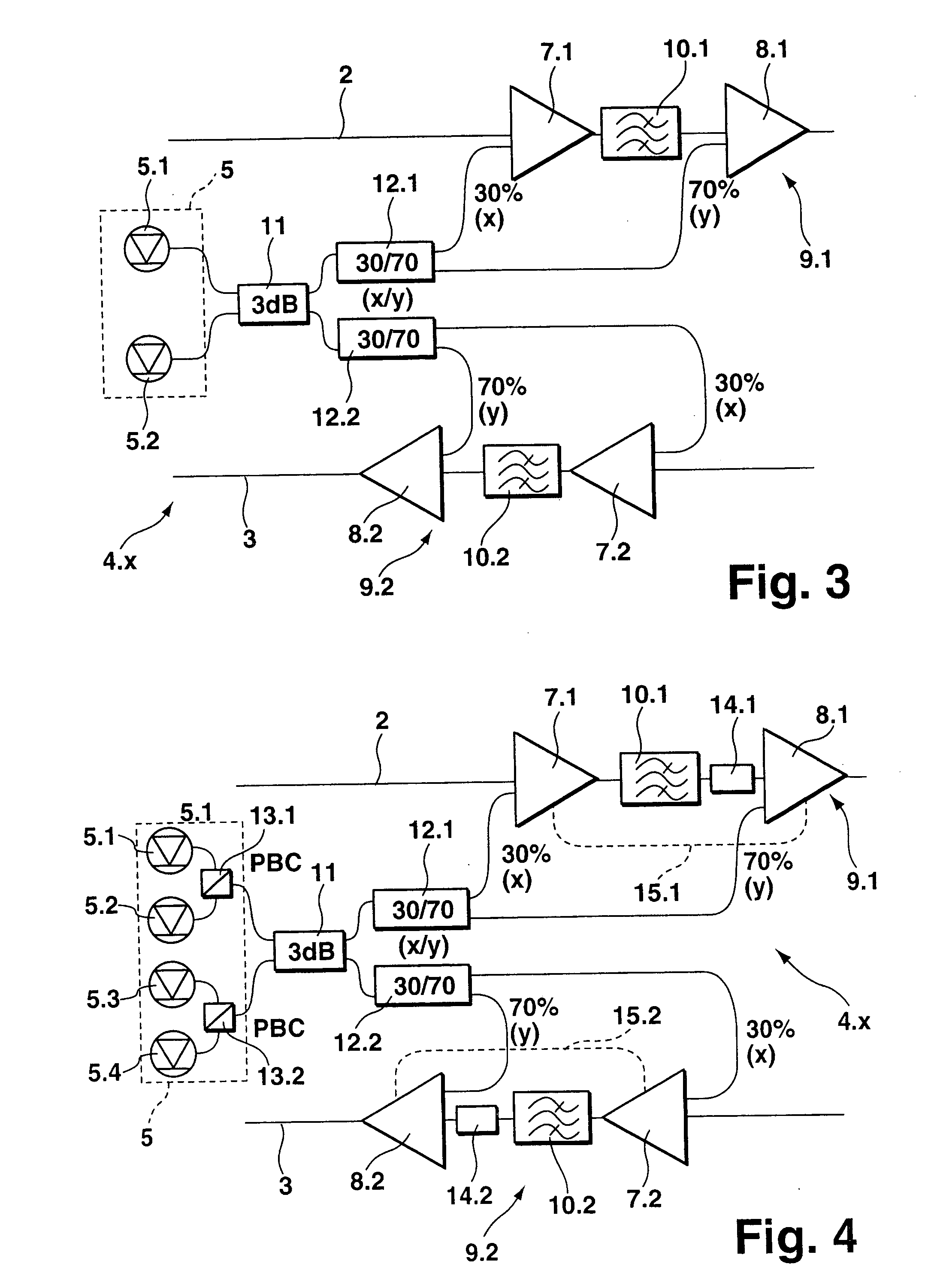
[0034]FIG. 3 shows a block diagram of the optical amplifier assembly 4.x in accordance with the present invention. The embodiment of FIG. 3 differs from the above-described embodiment of FIG. 2 in that a ratio of pump powers injected into the first and second fibre amplifiers of the first and second double stage fibre amplifiers are not equal. In particular, the pump power injected into the second fibre amplifiers 8.1, 8.2, i.e. the respective second stages of the double stage fibre amplifiers 9.1, 9.2, can be increased at the expense of the pump power injected into the respective first stages 7.1, 7.2. This solution is of particular interest when very large gains (>20 dB) are considered.

[0035] In the embodiment of FIG. 3 the optical amplifier assembly 4.x comprises two pump light sources 5.1, 5.2 forming a common pump source 5, which are coupled to a 3 dB-coupler, i.e. a 50:50 splitter 11. The 3 dB-coupler 11 evenly distributes the pump power of the common pump source 5 between two...


PUM


Abstract

An optical amplifier assembly for submarine applications. The optical amplifier assembly comprises: a first and a second double stage fibre amplifier with respective first and second fibre amplifiers for amplifying optical signals (OS, OS') each propagated on a respective optical fibre, said optical fibres being operated in opposite operating directions (W-E, E-W), and a common pump source comprising a plurality of pump light sources, the common pump source being coupled via a coupler as a co-propagating pump to the first and second fibre amplifiers of the first and second double stage fibre amplifiers. The proposed optical amplifier assembly further comprises a gain flattening filter between the two fibre amplifiers of the first and second double stage fibre amplifiers. Thus the proposed optical amplifier assembly presents an increased efficiency with respect to an output power at a constant pump power and allows to adjust the pump power for maintaining a given output power without excessive NF degradation.

Description

[0001] The invention is based on a priority application EP 05 292 484.2 which is hereby incorporated by reference. TECHNICAL FIELD [0002] The present invention relates to an optical amplifier assembly for submarine applications, comprising: a first and a second double stage fibre amplifier with respective first and second fibre amplifiers for amplifying optical signals each propagated on a respective optical fibre, said optical fibres being operated in opposite operating directions, and a common pump source comprising a plurality of pump light sources, the common pump source being coupled via a coupler as a co-propagating pump to the first and second fibre amplifiers of the first and second double stage fibre amplifiers. [0003] The invention also relates to an optical transmission system for submarine applications, comprising a first optical fibre for propagating optical signals in a first operating direction and a second optical fibre for propagating optical signals in a second ope...

Claims


Application Information

Patent Timeline
Patent Type & Authority Applications(United States)
IPC IPC(8): H01S3/00H04B10/12H04B10/291H04B10/294
CPCH04B10/2918H04B10/2941H04B10/298
Inventor CHARLET, GABRIELSIMONNEAU, CHRISTIANBECOUARN, LOIC
Owner RPX CORP
Learn More