
System and method for facilitating network performance analysis

a network performance and analysis system technology, applied in the field of networks, can solve the problems that the conventional system and method of determining and handling mos-lq scores do not adequately facilitate the determination of where the mos-lq score is degraded

Active Publication Date: 2007-05-24
CISCO TECH INC
View PDF23 Cites 19 Cited by
  • Summary
  • Abstract
  • Description
  • Claims
  • Application Information

AI Technical Summary

Problems solved by technology

Unfortunately, conventional systems and methods for determining and handling MOS-lq scores do not adequately facilitate determining where degradation of the MOS-lq score occurs in the overall network.

Method used


Image

  • System and method for facilitating network performance analysis
  • System and method for facilitating network performance analysis
  • System and method for facilitating network performance analysis

Examples


first embodiment

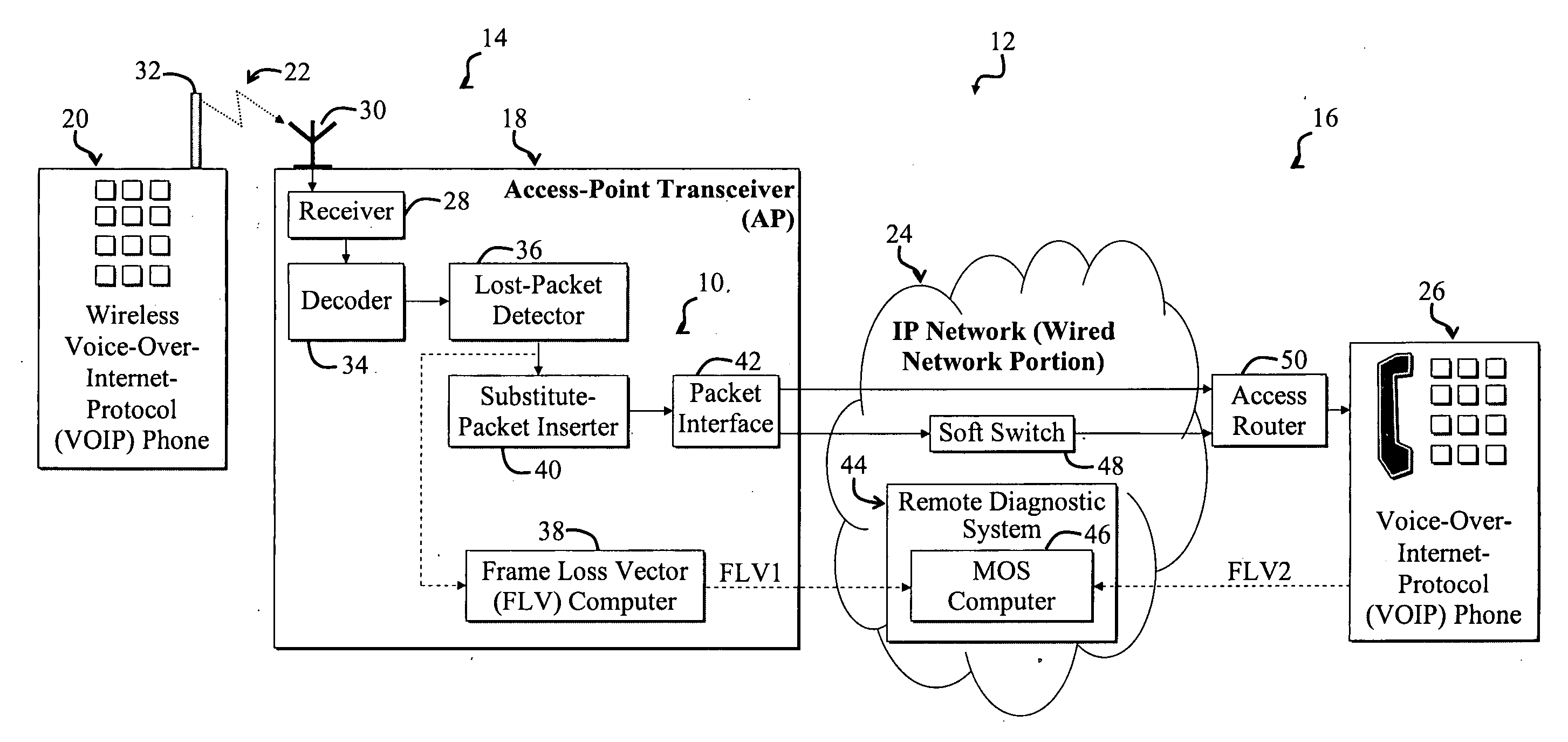
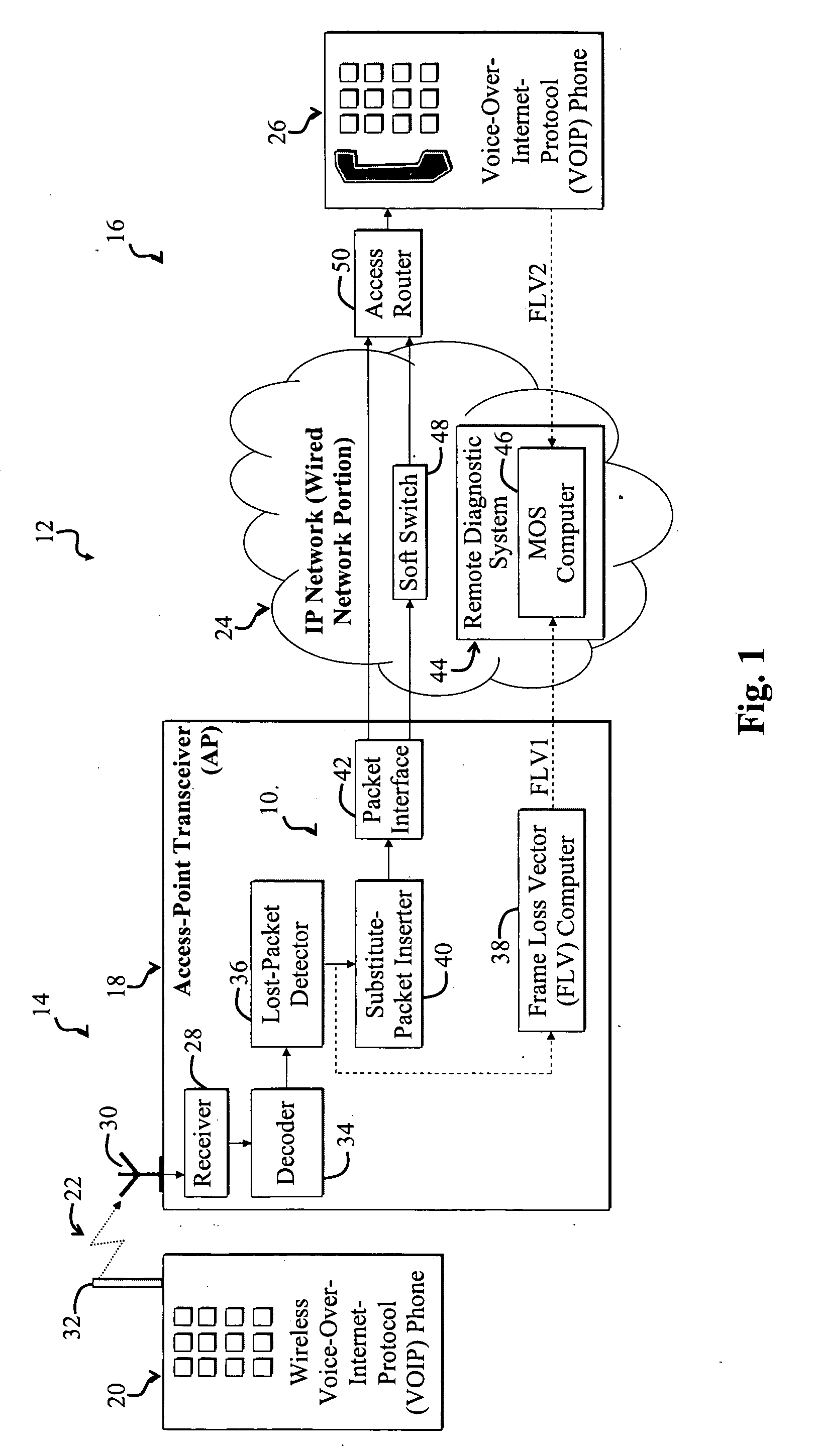
[0014]FIG. 1 is a diagram illustrating a system 10 for determining communications link quality over different portions 14, 16 of a network 12 according to the present invention. The system 10 is implemented via the network 12. The network 12 includes a first wireless portion 14 and a second wired portion 16. The first portion 14 of the network 12 includes a wireless Access Point transceiver (AP) 18 in communication with a Voice-Over-Internet-Protocol (VOIP) phone 20 via a wireless communication link 22. The wired portion 16 of the network 12 includes an Internet Protocol (IP) network 24, such as the Internet, which is connected to a wired VOIP phone 26. The IP network 24 may be implemented via another type of packet-based or cell-based network without departing from the scope of the present invention.

[0015] In the present specific embodiment, the wireless AP 18 includes a receiver 28, which receives input from an AP antenna 30. The AP antenna 30 receives transmissions from the VOIP ...

third embodiment

[0055]FIG. 6 is a diagram illustrating a system 150 for determining network communications link quality over different portions of a network 152 according to the present invention. The operative scenario illustrated in FIG. 6 is related to the operative scenarios of FIGS. 1 and 3 with the exception that the communications link in question occurs from the wired VOIP phone 26 to the wireless VOIP phone 20 instead of vice versa. Furthermore, reporting of FLVs and associated computation of MOS scores by the MOS computer 46 is selectively controlled based on link performance and with reference to an adjustable performance threshold as discussed more fully below. Alternatively, FLVs are reported periodically. The wireless VOIP phone 20 and AP 18 of FIG. 1 are replaced with a modified wireless VOIP phone 160 and AP 168, respectively, in FIG. 6.

[0056] Transmit portions of the AP 168 and the wireless VOIP phone 160 are illustrated in FIG. 6. The transmit section of the AP 168 includes the pa...


PUM


Abstract

A system for facilitating network performance analysis. In an illustrative embodiment, the system includes a first module capable of quantifying network performance associated with a first portion of the network and providing a signal in response thereto. A second module is capable of ascertaining performance degradations in a communications link traversing plural portions of the network that are attributable to the first portion based on the signal. In a more specific embodiment, the second module further includes a third module adapted to ascertain degradations in network performance associated with a second portion of the network based on the signal and based on a performance parameter associated with both the first portion and the second portion of the network. In this embodiment, the first portion includes a wireless portion, and the second portion includes a wired portion. The performance parameter incorporates a Frame Loss Vector (FLV) associated with a communications link that traverses the wireless and wired portions of the network.

Description

BACKGROUND OF THE INVENTION [0001] This invention is related in general to networks and more specifically to systems and methods for observing or measuring network performance or communications link quality. [0002] Systems for observing communications link quality are employed in various demanding applications including power-control systems for cellular networks and problem-diagnosis systems for Voice Over Internet Protocol (VOIP) communications sessions. Such applications often demand accurate network-quality observation systems that facilitate determining where and when communications link quality has degraded. [0003] Network-quality observation systems are particularly important in VOIP applications, where a given communication session may employ plural types of networks, including wireless and wired networks, each with different performance characteristics. An exemplary VOIP system includes a first endpoint and a second endpoint, such as a wireless VOIP phone and a wired VOIP p...

Claims


Application Information

Patent Timeline
Patent Type & Authority Applications(United States)
IPC IPC(8): H04L12/26H04L12/66H04J1/16
CPCH04L43/0829H04L43/106H04L43/16
Inventor RAMALHO, MICHAEL A.
Owner CISCO TECH INC
Learn More