Video encoding/decoding method and apparatus

a video and encoding technology, applied in the field of video encoding/decoding methods, can solve the problems of inability to select the high band stopping characteristic of the low-pass filter in the motion compensation temporal filter according to the high band stopping characteristic of the low-pass filter in the motion compensation filter

Inactive Publication Date: 2007-05-24
KK TOSHIBA
View PDF0 Cites 44 Cited by
  • Summary
  • Abstract
  • Description
  • Claims
  • Application Information

AI Technical Summary

Problems solved by technology

Therefore, when an inverse motion vector is obtained, mismatching between corresponding pixels may occur between a high-pass filter and a low-pass filter.
However, any of the above conventional techniques does not control a high band stopping characteristic of the low-pass filter based on coarseness of quantization.
As described above, there is a problem a high band stopping characteristic of a low-pass filter in a motion compensated temporal filter cannot be selected according to coarseness of quantization by a conventional technology.
There is a problem a threshold value in the control function for controlling a low-pass filter coefficient concerning a motion compensated error and a motion vector cannot be adaptively selected every plural frames / fields or every single frame / field.

Method used


Image

  • Video encoding/decoding method and apparatus
  • Video encoding/decoding method and apparatus
  • Video encoding/decoding method and apparatus

Examples


first embodiment

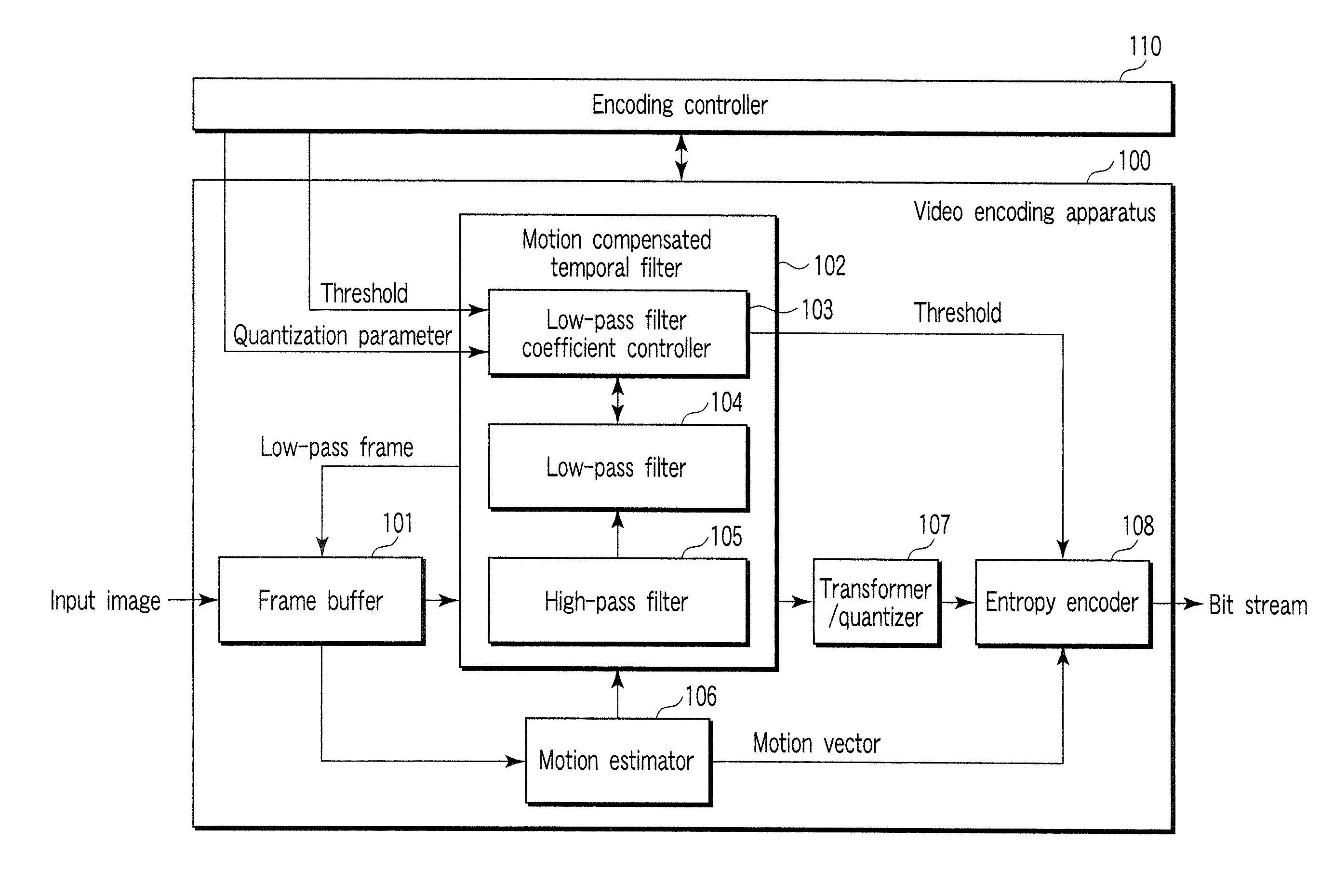
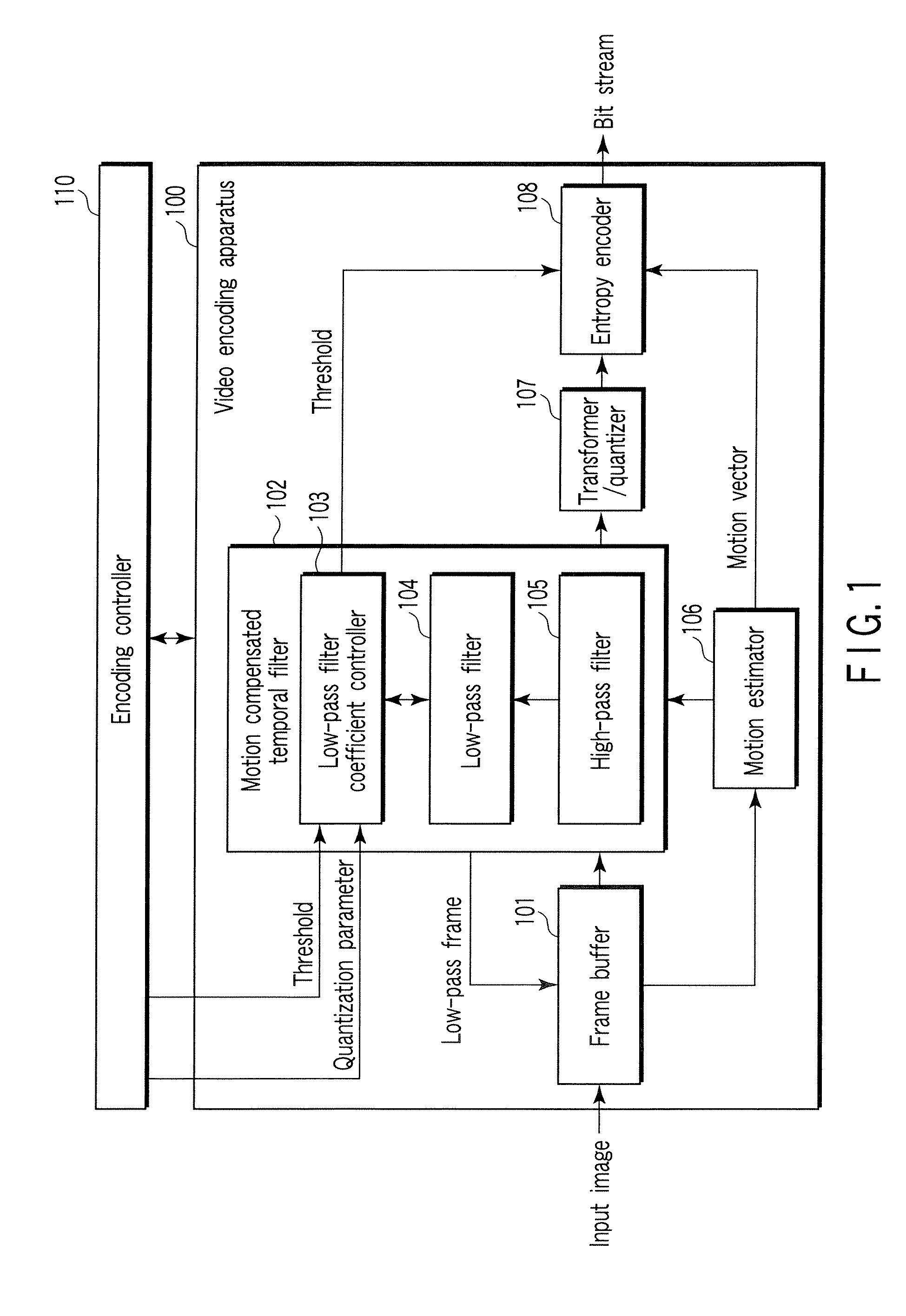
[0038] The video encoding apparatus 100 shown in FIG. 1 comprises a frame buffer 101, a motion compensated temporal filter 102, a low-pass filter coefficient controller 103, a low-pass filter 104, a high-pass filter 105, a motion estimator 106, a transformer / quantizer 107, an entropy encoder 108, and an encoding controller 110 for controlling them. This encoding controller 110 performs quantization parameter control, etc. on the high-pass frame and low-pass frame, and controls the entire encoding.

[0039] The frame buffer 101 stores frames fetched from an input video image for one GOP. Alternatively, when the low-pass frame generated with the motion compensated temporal filter 102 is divided into a high-frequency component and low-frequency component in temporal direction further, the frame buffer 101 stores the generated low-pass frame.

[0040] The motion estimator 106 performs motion estimation to generate a prediction error signal with the high-pass filter 105 in the motion compens...

second embodiment

[0059] In the second embodiment shown in FIG. 7, a temporal low-pass filter for motion compensated temporal filtering is configured to execute filtering as preprocessing of a conventional video encoding system (H.264 / AVC, for example).

[0060] A motion compensated temporal filter 102, a low-pass filter coefficient controller 103, a low-pass filter 104, a high-pass filter 105 and a motion estimator 106 are similar to those of the first embodiment. Because the process of the low-pass filter coefficient controller 103 and low-pass filter unit 104 are similar to that shown by the flowchart of FIG. 2, detail description is omitted.

[0061] A frame buffer 701 acquires a frame for 1 GOP to be encoded from an input video image or a low-pass frame generated with the motion compensated temporal filter 102. A video encoding apparatus 700 encodes a frame for 1 GOP acquired from a frame buffer 701 and subjected to temporal direction low-pass filtering.

[0062] A motion compensator 702 performs moti...

third embodiment

[0068] The video decoding apparatus 800 shown in FIG. 8 comprises a frame buffer 801, a motion compensated temporal synthesis filter unit 802, a low-pass synthesis filter coefficient controller 803, a low-pass synthesis filter 804, a high-pass synthesis filter 805, an inverse transformer / dequantizer 807, and an entropy decoder 808, and is controlled with the decoding controller 810.

[0069] The entropy decoder 808 decodes information such as a quantized transform coefficient, a motion vector, a prediction mode, a quantization parameter, a threshold value, which are acquired from the bit stream. The inverse transformer / dequantizer 807 dequantizes the quantized transform coefficient based on the quantization parameter acquired from the entropy decoder 808 and inverse-transforms the generated transform coefficient to reconstruct the high-pass frame and low-pass frame (including a quantization error).

[0070] The frame buffer 801 acquires the high-pass frame and low-pass frame for 1 GOP f...


PUM


Abstract

A video encoding method includes subjecting an input video image to motion compensated temporal filtering using a motion compensated temporal filter to produce a low-pass filtered image, quantizing a transform coefficient of the low-pass filtered image, encoding a quantized transform coefficient, calculating a weight to be given to a low-pass filter coefficient of a low-pass filter of the motion compensated temporal filter according to coarseness of quantization and a magnitude of a motion compensated error, and controlling a high band stopping characteristic of the low-pass filter according to the low-pass filter coefficient weighted by the weight, wherein the controlling controls the high band stopping characteristic of the low-pass filter to provide a positive correlation with respect to the quantization parameter and provide a negative correlation with respect to the magnitude of the motion compensated error.

Description

CROSS-REFERENCE TO RELATED APPLICATIONS [0001] This application is based upon and claims the benefit of priority from prior Japanese Patent Application No. 2005-338775, field Nov. 24, 2005, the entire contents of which are incorporated herein by reference. BACKGROUND OF THE INVENTION [0002] 1. Field of the Invention [0003] The invention relates to a video encoding / decoding method using a temporal filter with motion compensation and an apparatus for the same. [0004] 2. Description of the Related Art [0005] In recent years, a video encoding / decoding technique using a motion compensated temporal filtering (MCTF) attracts attention. MCTF performs a motion compensated temporal subband decomposition to divide an input video image into a high frequency component (prediction error frame) and a low frequency component (average frame) with respect to a temporal direction. The decoding does an inverse operation from the encoding, that is, synthesizes the high frequency component and the low fr...

Claims


Application Information

Patent Timeline
Patent Type & Authority Applications(United States)
IPC IPC(8): H04N11/02H04N19/50H03M7/36H04N19/117H04N19/134H04N19/136H04N19/137H04N19/139H04N19/189H04N19/196H04N19/46H04N19/503H04N19/60H04N19/61H04N19/615H04N19/625H04N19/63H04N19/70H04N19/80H04N19/91
CPCH04N19/139H04N19/13H04N19/63H04N19/61H04N19/615H04N19/137H04N19/80H04N19/85H04N19/117
Inventor WADA, NAOFUMIKODAMA, TOMOYA
Owner KK TOSHIBA
Why Eureka
Try Eureka