Optical apparatus

a technology of optical equipment and optical shutter, which is applied in the field of optical equipment, can solve the problems of simple mechanical shutter, short exposure time, and short exposure time, and achieve the effect of accurate calculation and actual exposure tim

Inactive Publication Date: 2007-05-24
CANON KK
View PDF1 Cites 38 Cited by
  • Summary
  • Abstract
  • Description
  • Claims
  • Application Information

AI Technical Summary

Benefits of technology

[0018] According to another exemplary embodiment of the present invention, even when a shutter is equipped with no position detector and can only control the open and close positions based on mechanical contact, the actual exposure time can be accurately calculated based on the acceleration of the shutter and the temporal change of the diaphragm aperture caused by the shutter.

Problems solved by technology

On the other hand, the mechanical shutter requires a relatively long time to completely close.
However, if the opening action and the closing action are mutually different, an actual change of the light exposure may deviate from a trapezoidal area.
Thus, using the approximation with a trapezoidal area will cause errors.
However, a simple mechanical shutter, if equipped with no STM, cannot detect an intermediate position of the shutter during a shifting operation.
Thus, the simple mechanical shutter can only rely on mechanical contact to detect opened and closed positions.
Furthermore, unequivocally controlling the action of a mechanical shutter is difficult.
Thus, the conventional method for calculating the actual exposure time cannot be directly applied to this kind of mechanical shutter.
However, the conventional calculation method cannot be applied to the accelerated motion type.
As described above, when a mechanical shutter having a simple control mechanism and causing accelerated motion is used, accurately calculating the actual light exposure is difficult.

Method used


Image

  • Optical apparatus
  • Optical apparatus
  • Optical apparatus

Examples


Embodiment Construction

[0030] The following description of exemplary embodiments, features and aspects of the present invention is merely illustrative in nature and is in no way intended to limit the invention, its application, or uses.

[0031] It is noted that throughout the specification, similar reference numerals and letters refer to similar items in the following figures, and thus once an item is defined in one figure, it may not be discussed in following figures.

[0032] Various exemplary embodiments, features, and aspects of the invention will now herein be described in detail below with reference to the drawings.

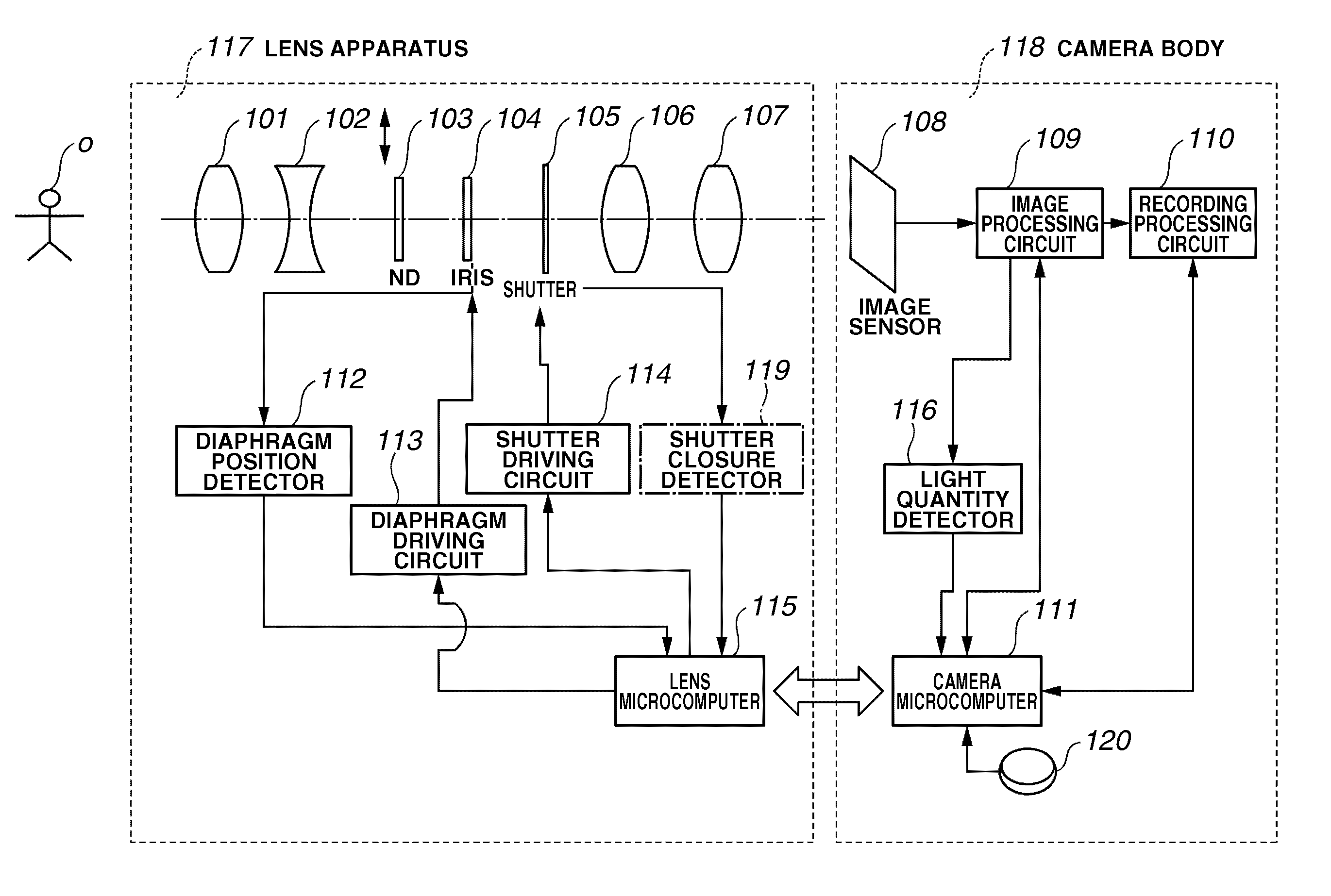
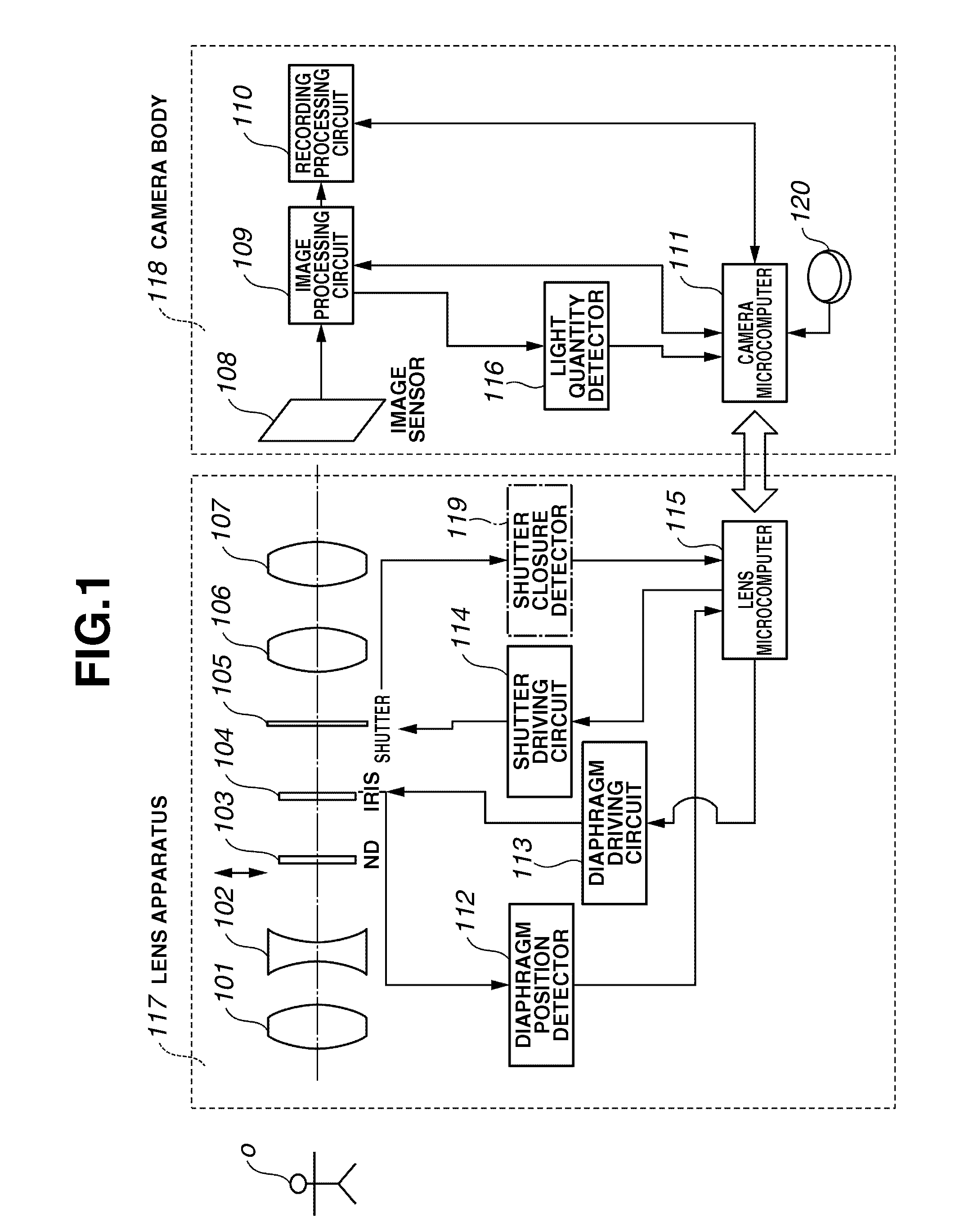
[0033]FIG. 1 shows an exemplary lens interchangeable imaging system, according to which a lens apparatus 117 is detachably mounted on a camera body (imaging apparatus) 118.

[0034] First, light arriving from an object “O” enters the lens apparatus 117, in which the light successively passes through optical members of an imaging optical system. Then, the light enters the camera body 118. The ...


PUM


Abstract

An optical apparatus includes a mechanical shutter in addition to a mechanical diaphragm. The optical apparatus obtains a shutter shifting amount based on acceleration data of the shutter, obtains a total light exposure in a period of time required for the shutter to completely close an aperture of the diaphragm having a predetermined F-number, and calculates an actual exposure time by dividing the total light exposure by a light exposure per unit time calculated from an aperture area of the diaphragm having the predetermined F-number in an opened state.

Description

BACKGROUND OF THE INVENTION [0001] 1. Field of the Invention [0002] The present invention relates to an optical apparatus, such as a video camera, which can perform a still image shooting operation based on a fixed F-number using a mechanical shutter and an electronic shutter. [0003] 2. Description of the Related Art [0004] Advanced video cameras have the capability of shooting high resolution still images in addition to the capability of shooting moving images. The still image shooting operation of the video camera is generally realized by combining a mechanical shutter and an electronic shutter. The electronic shutter can control the start timing and the reset timing of storing an electric charge in an image sensor. [0005] With the combination of a mechanical shutter and an electronic shutter, even a video camera equipped with an image sensor which cannot perform interlace shooting can realize a progressive still image shooting operation (see Japanese Patent Application Laid-Open ...

Claims


Application Information

Patent Timeline
Patent Type & Authority Applications(United States)
IPC IPC(8): G03B7/093
CPCG03B7/093G03B9/06G03B9/08G03B17/14G03B43/02H04N5/23209H04N5/2353H04N5/238H04N23/663H04N23/75H04N23/73
Inventor UCHIYAMA, MINORU
Owner CANON KK
Why Eureka
Try Eureka