
Image heating apparatus

a heating apparatus and image technology, applied in the field of image heating apparatus, can solve the problems of heater cracking, heater breaking, and insufficient reinforcement of the periphery of the hole into which the thermosensitive element is to be fitted, so as to prevent heater cracking

Active Publication Date: 2007-05-24
CANON KK
View PDF5 Cites 5 Cited by
  • Summary
  • Abstract
  • Description
  • Claims
  • Application Information

AI Technical Summary

Benefits of technology

[0019] The present invention has been made in view of the above described problems, and has as an object to provide an image heating apparatus in which cracking of the heater can be prevented.

Problems solved by technology

For this reason, a high stress acts on the portion of the heater 1000 that is adjacent to the portion of the heater holder provided with the hole, which leads to cracking of the heater 1000.
However, in the case where the rigidity of the heater holder is ensured to some extent, reinforcing the periphery of the hole into which the thermosensitive element is to be fitted is not sufficient in preventing cracking of the heater, in some cases.
Thus, the stress acting on the portion of the heater adjacent to the hole and its periphery becomes high, and there is a possibility that the heater may break.
As per the above, the conventional solution is not effective in the case where the phenomenon that the heater sinks into the heater holder due to softening of the heater seating surface of the heater holder occurs rather than bending of the heater holder.
When the power supplied to the heater becomes large, if the fixing device becomes uncontrollable for failure of a temperature control system or other reasons and a large amount of power is continuously supplied to the heater, high temperatures at which the seating surface of the heater holder easily melts are reached.
Therefore, cracking of the heater can occur, in some cases, before the thermosensitive element such as a thermostatic switch works.
When cracking of the heater occurs in this way, the heater cannot be used any longer, which is disadvantageous from the viewpoint of recycling of parts.
In addition, there is the problem that a sufficient distance cannot be left between a portion to which the primary voltage is applied via a thermistor or the like provided on the heater and the secondary circuit or the ground portion.
This sometimes leads to breakage of the secondary circuit, and an additional repair cost may be incurred.

Method used


Image

  • Image heating apparatus
  • Image heating apparatus
  • Image heating apparatus

Examples


first embodiment

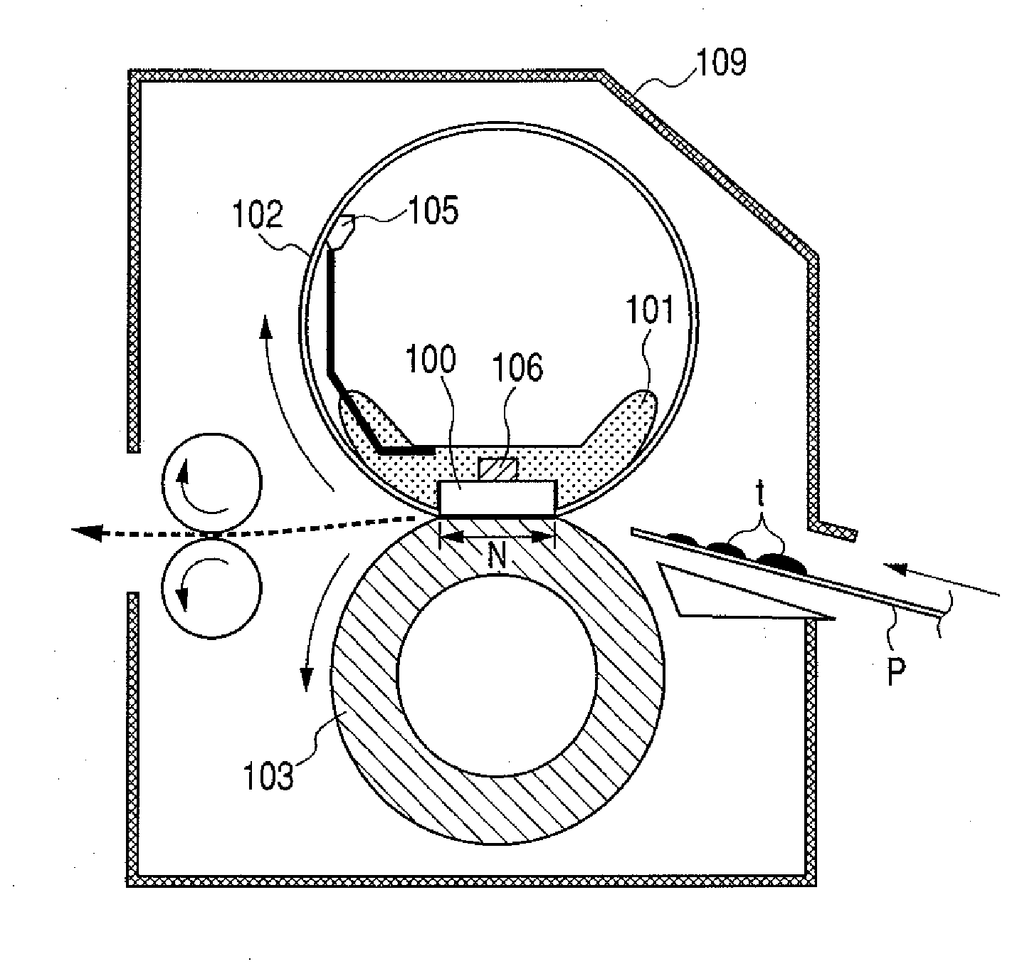
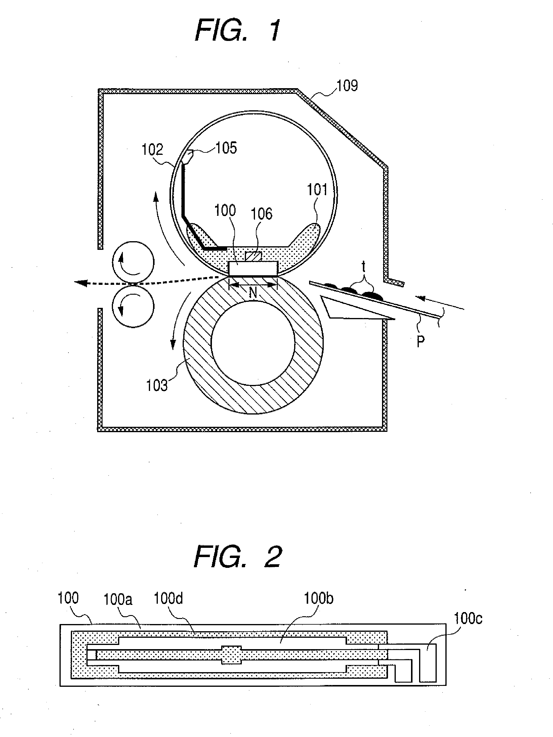
[0036] (Description of Structure of Fixing Device)

[0037] A fixing device according to a first embodiment of the present invention will be described with reference to FIGS. 1 and 2.

[0038]FIG. 1 is a cross sectional view of the fixing device according to the first embodiment. FIG. 2 is a plan view showing the longitudinal surface of the heater in the first embodiment.

[0039] The fixing device according to the first embodiment is comprised of a heater 100, a heater holder 101, a fixing belt (or flexible sleeve) 102, a pressure roller (or elastic roller) 103 and thermistors (or thermosensitive elements) 105, 106.

[0040] The heater 100 is comprised of a substrate 100a, a heat generating resistor 100b, an electrode 100c and an insulation coating layer 100d as shown in FIG. 2.

[0041] The substrate 100a may be made of an insulating ceramic material such as alumina or aluminum nitride. In this embodiment, use is made of a longitudinal aluminum nitride substrate having a thickness of 0.6 mm...

second embodiment

[0091] The second embodiment is characterized by that heater support portions and a heater holder are integrally molded.

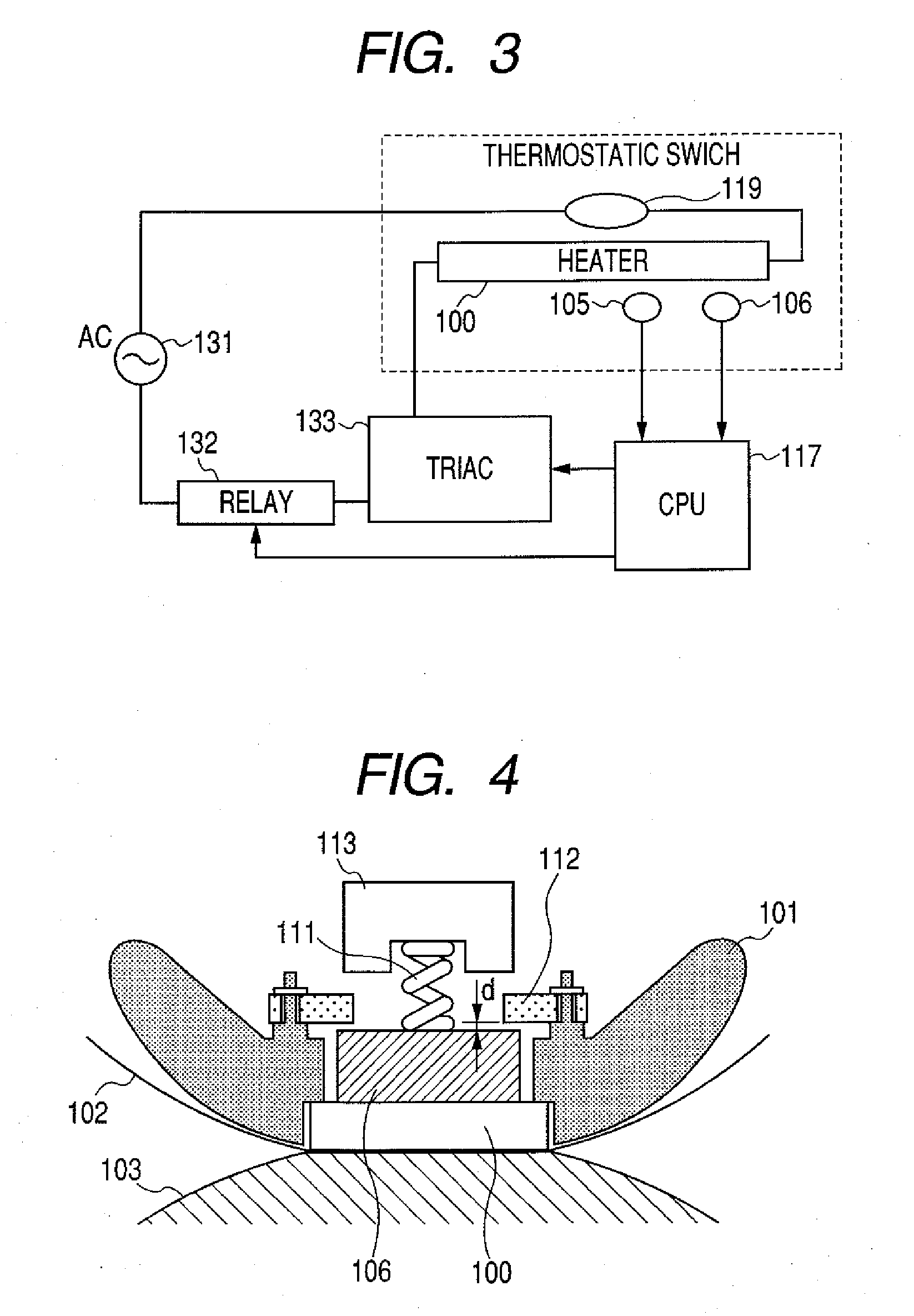
[0092]FIG. 5 is a cross sectional view of a fixing device according to this embodiment taken near the position at which a sub thermistor is provided.

[0093] The heater support portions 1120 and the heater holder 501 are integrally molded, and therefore dimensions along the vertical directions can be controlled finely. Thus, it is possible to define the clearance d between the sub thermistor 106 and the heater support member finely, and stable support of the heater can be expected when abnormal temperature rise of the heater occurs.

[0094] In the structure of this embodiment, it is possible to make the clearance d smaller than that in the first embodiment. In the second embodiment, the clearance between the sub thermistor 106 and the heater support member is designed to be 0.05 mm.

[0095] (Result of Excessive Power Supply Test)

[0096] We conducted the excessive pow...

third embodiment

[0100] The fixing device used in the third embodiment is substantially the same as that in the second embodiment, except that a recess is provided on the heater contact surface of the heater holder so that a layer of air is present between the heater and the heater holder.

[0101]FIG. 6A is a cross sectional view of the fixing device according to this embodiment taken near the position at which the sub thermistor is provided. FIG. 6B is a cross sectional view of the fixing device taken at a position at which the sub thermistor is not provided.

[0102] As shown in FIG. 6B, the heater seating surface of the heater holder 601 is constructed in such a way that an air layer G is formed between the heater 100 and the heater holder 601. This structure is intended to reduce the transmission of heat generated by the heater 100 to the heater holder 601 to thereby enhance heat efficiency.

[0103] In this embodiment, the clearance d between the sub thermistor 106 and the heater support portions 11...


PUM


Abstract

The invention prevents cracking of heater that may occur when a fixing device becomes uncontrollable and provides an image forming apparatus that is advantageous from the viewpoint of recycling of parts. A heater support member that supports a heater during abnormal temperature rise is provided at a position at which a heater holder deforms greatly when abnormal temperature rise of the heater occurs.

Description

[0001] This application is a continuation of International Application No. PCT / JP2006 / 315244, filed Jul. 26, 2006, which claims the benefit of Japanese Patent Application No. 2005-216150, filed Jul. 26, 2005.BACKGROUND OF THE INVENTION [0002] 1. Field of the Invention [0003] The present invention relates to an image heating apparatus that can be suitably used as a heat fixing device equipped in a copying machine or a printer, and more particularly to an image heating apparatus provided with a heater having a heat generating resistor provided on a substrate and an elastic roller that forms, in cooperation with the heater, a nip portion through which a recording material that bears an image is conveyed. [0004] 2. Description of the Related Art [0005] A film type fixing device has been practically used as a fixing device equipped in a copying machine or a printer. The film type fixing device has a heater made of a ceramic material, a fixing film made of polyimide or stainless steel etc...

Claims


Application Information

Patent Timeline
IPC IPC(8): G03G15/20
CPCG03G2215/2016G03G15/2039G03G2215/2035
Inventor MOCHIZUKI, KEISUKESUZUKI, JUNJI
Owner CANON KK
Learn More