Method and apparatus for wind turbine braking

US20070116572A1Active Publication Date: 2007-05-24GENERAL ELECTRIC CO

Image

  • Method and apparatus for wind turbine braking
  • Method and apparatus for wind turbine braking
  • Method and apparatus for wind turbine braking

Examples


Embodiment Construction

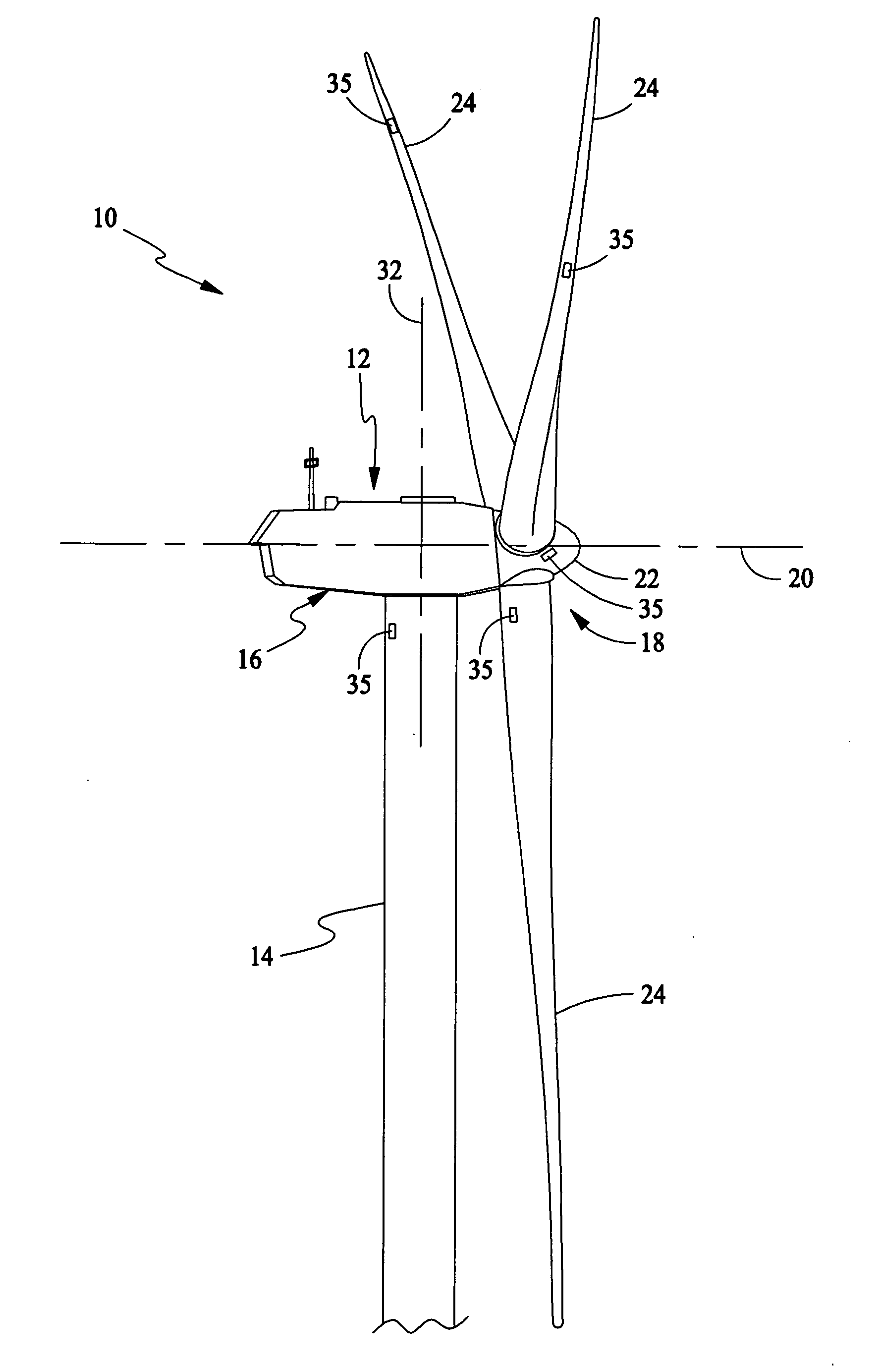
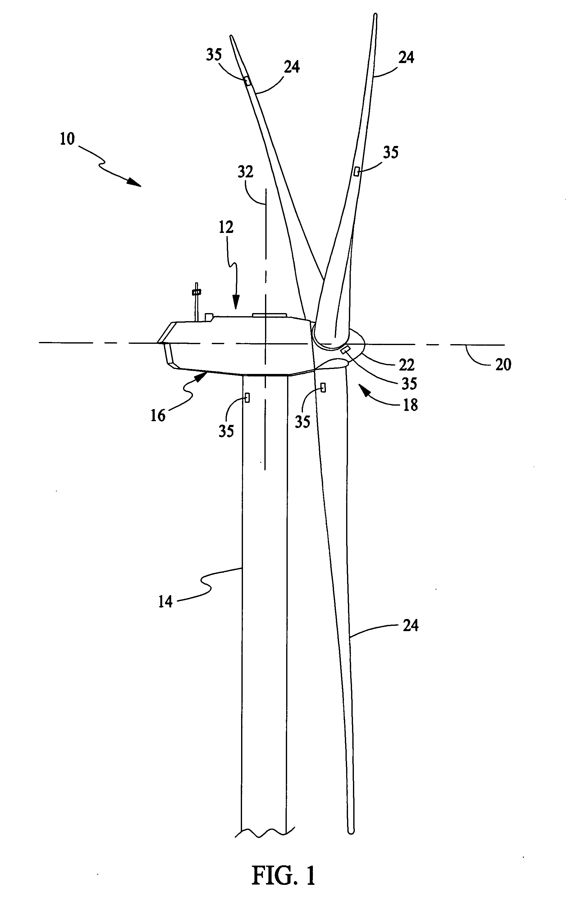
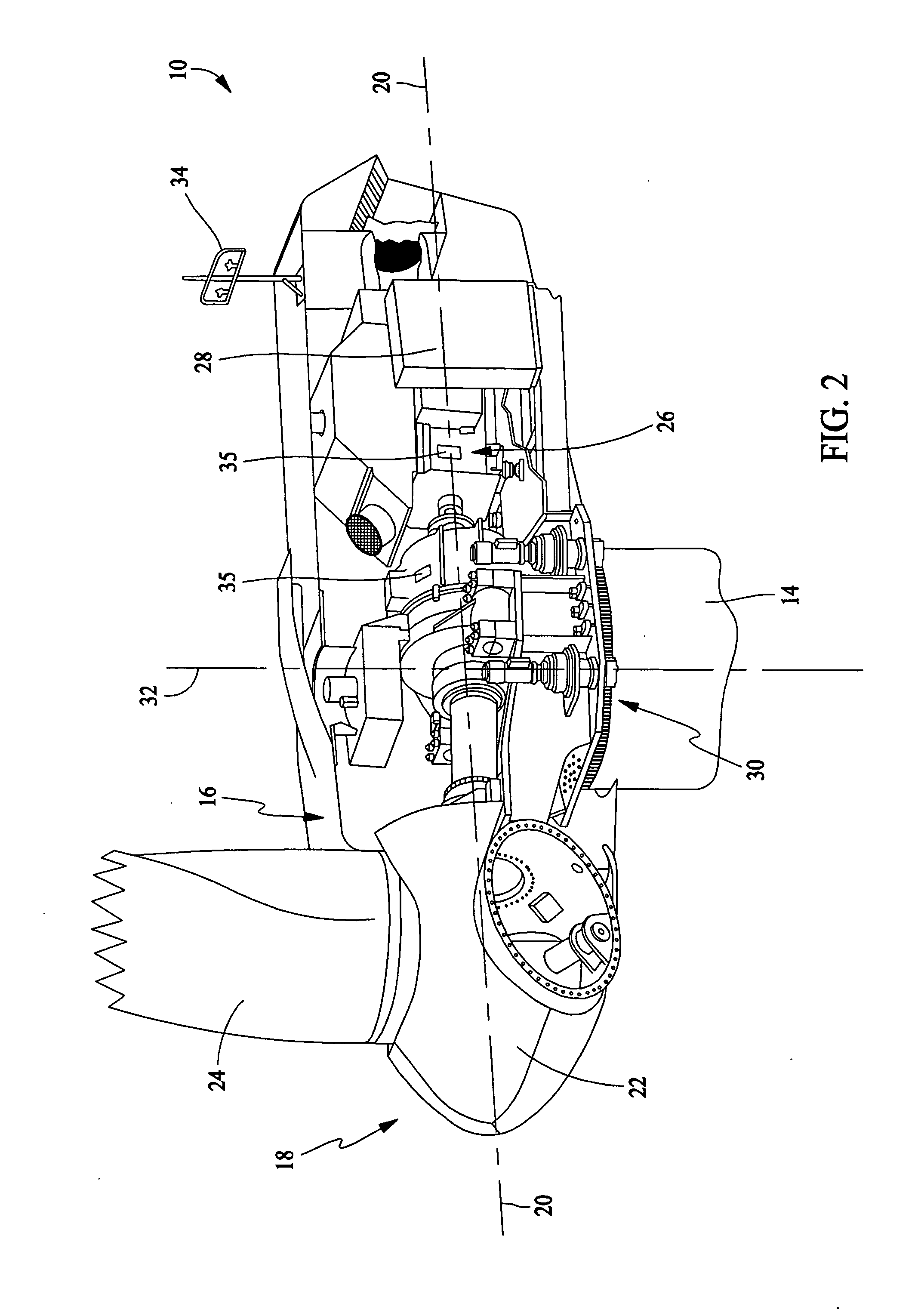
[0012] As used herein, the term “blade” is intended to be representative of any device that provides reactive force when in motion relative to a surrounding fluid. As used herein, the term “wind turbine” is intended to be representative of any device that generates rotational energy from wind energy, and more specifically, converts kinetic energy of wind into mechanical energy. As used herein, the term “wind generator” is intended to be representative of any wind turbine that generates electrical power from rotational energy generated from wind energy, and more specifically, converts mechanical energy converted from kinetic energy of wind to electrical power. As used herein, the term “windmill” is intended to be representative of any wind turbine that uses rotational energy generated from wind energy, and more specifically mechanical energy converted from kinetic energy of wind, for a predetermined purpose other than generating electrical power, such as, but not limited to, pumping ...


PUM


Abstract

A method for braking a wind turbine including at least one rotor blade coupled to a rotor. The method includes selectively controlling an angle of pitch of the at least one rotor blade with respect to a wind direction based on a design parameter of a component of the wind turbine to facilitate reducing a force induced into the wind turbine component as a result of braking.

Description

STATEMENT REGARDING FEDERALLY SPONSORED RESEARCH & DEVELOPMENT [0001] The U.S. Government has certain rights in this invention as provided for by the terms of Contract No. DE-AC36-98GO10337 awarded by the Department of Energy / National Renewable Energy Laboratory Division.BACKGROUND OF THE INVENTION [0002] This invention relates generally to wind turbines, and more specifically to methods and apparatus for wind turbine braking. [0003] At least some known wind turbines may include redundant braking systems to satisfy safety requirements. For example, at least some known wind turbines include a disk brake to facilitate stopping a wind turbine rotor against full wind torque, and a stored energy source, such as hydraulic accumulators, stored spring energy, capacitors, and / or batteries, to enable braking during a power failure. Moreover, at least some known wind turbines also include a braking system that aerodynamically brakes the rotor by pitching the rotor blades into a feathered posit...

Claims


Application Information

Patent Timeline
24 May 2007
Publication
US20070116572A1
IPC
B63H1/06
CPC
F03D7/0224; F03D7/024; F03D7/0244; F03D7/0252; F03D7/0264; F03D7/042; F05B2260/901; F05B2270/1071
Inventors
BARBU, CORNELIU; TEICHMANN, RALPH