Fuel cell stack having coolant passage whose lower area has larger flow resistance

a fuel cell and coolant passage technology, applied in the field of fuel cell stacks, can solve the problem that the electric power generation cannot be performed uniformly, and achieve the effect of less cooling, stable power generation, and relative humidity in the lower portion of reaction gas passages

Active Publication Date: 2007-05-24
HONDA MOTOR CO LTD
View PDF3 Cites 8 Cited by
  • Summary
  • Abstract
  • Description
  • Claims
  • Application Information

AI Technical Summary

Benefits of technology

[0019] In accordance with the above structure, the amount of coolant flowing in the lower area of the coolant passage can be smaller than the amount of coolant flowing in the upper area thereof. Therefore, the lower portion of the fuel gas passage, the oxidant gas passage, and the membrane electrode assembly (called “the reaction gas passages and the like” below) can be less cooled in comparison with the upper portion, so that the temperature of the above lower portion which includes a larger amount of water can be higher than that of the above upper portion which includes a smaller amount of water. As a result, the relative humidity in the lower portion of the reaction gas passages and the like can be reduced and substantially equal to that in the upper portion thereof. Accordingly, it is possible to provide a substantially uniform relative humidity over the whole plane of the membrane electrode assembly, and electric power generation can be performed uniformly over the whole plane of the membrane electrode assembly, thereby performing stable power generation. In addition, it is possible to prevent the membrane electrode assembly from drying, and also to prevent the reaction gas passages from being closed or blocked due to the generated water.
[0020] In addition, as the lower area of the coolant passage has a larger flow resistance in comparison with the upper area, the flow resistance of the reaction gas passages is also larger in the lower area in comparison with the upper area. Therefore, the pressure of the reaction gases in the lower area can be reduced, and can be saturated partial pressure of water vapor or lower; thus, water (e.g., the generated water) existing in the reaction gas passages of the lower area can be vaporized and discharged from the reaction gas passages together with the reaction gases.

Problems solved by technology

When such a difference in humidity occurs in the fuel cell stack, the electric power generation cannot be performed uniformly.

Method used


Image

  • Fuel cell stack having coolant passage whose lower area has larger flow resistance
  • Fuel cell stack having coolant passage whose lower area has larger flow resistance
  • Fuel cell stack having coolant passage whose lower area has larger flow resistance

Examples


Embodiment Construction

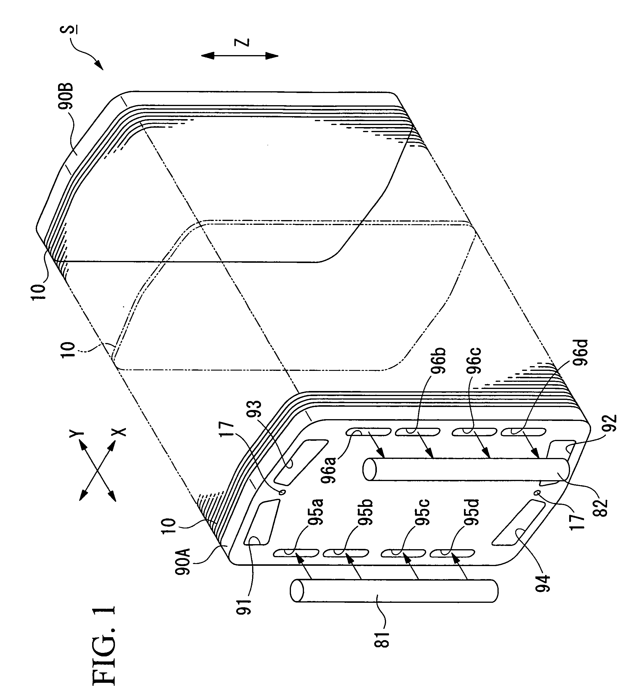
[0032] Hereinafter, an embodiment of a fuel cell stack in accordance with the present invention will be described with reference to the appended FIGS. 1 to 8. A fuel cell stack “S” of this embodiment is used in a fuel cell automobile.

[0033]FIG. 1 is a general perspective view of the fuel cell stack S in which a number of unit fuel cells 10 (called “unit cells” below) are stacked and electrically connected in series, end plates 90A and 90B interpose the stacked body, and these elements are fastened together using tie rods (not shown). In each unit cell 10, longitudinal sides are longer than lateral sides. The fuel cell stack S of this embodiment is installed in the vehicle while the longitudinal sides thereof are arranged vertically (i.e., in the gravitational direction). In the appended figures, arrows X and Y indicate horizontal directions, and arrow Z indicates a vertical direction.

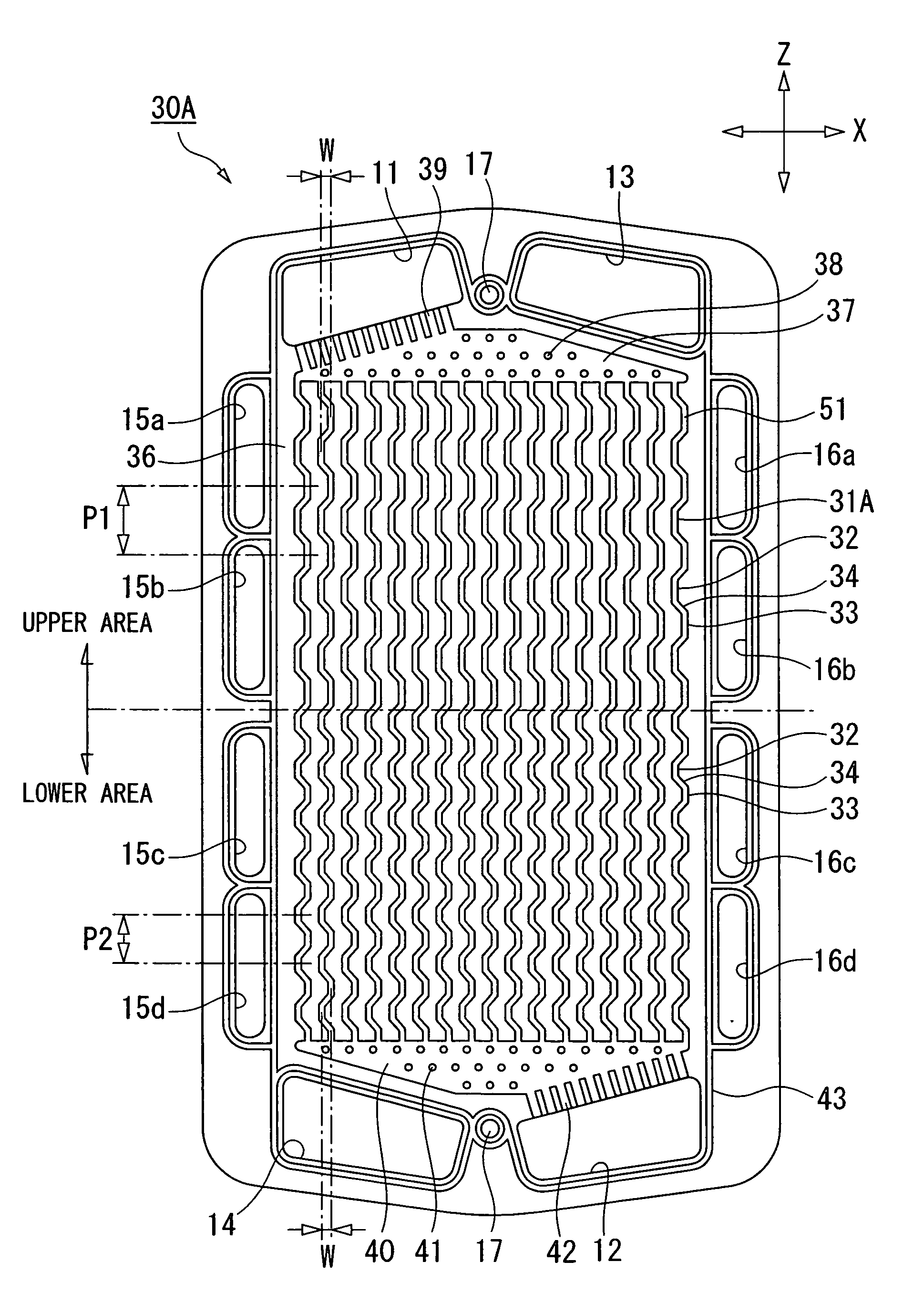
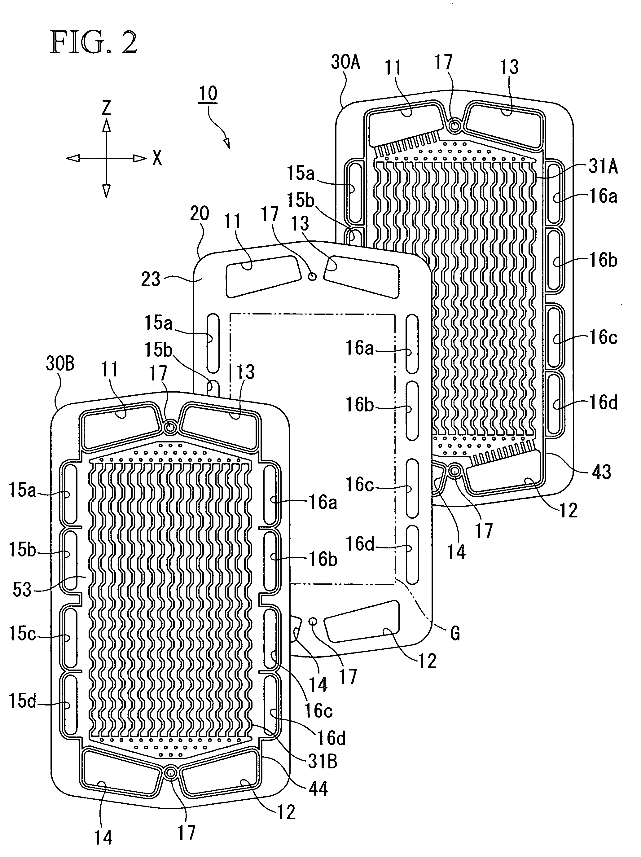
[0034] As shown in FIG. 2, each of the unit cells 10 has a sandwich structure in which a membrane ...


PUM

PropertyMeasurementUnit
flow resistanceaaaaaaaaaa
areaaaaaaaaaaa
shapeaaaaaaaaaa

Abstract

A fuel cell stack having stacked unit fuel cells, each having a pair of separators between which a membrane electrode assembly is provided, which includes an anode and a cathode. Each separator has protruding lines arranged vertically in a zigzag manner, which protrude in a direction going away from the membrane electrode assembly. A space between the anode and the protruding lines of the separator facing the anode is used as a fuel gas passage. A space between the cathode and the protruding lines of the separator facing the cathode is used as an oxidant gas passage. At least part of the separators are each arranged in close contact with another separator so that a coolant passage through which a coolant flows horizontally is formed between both separators. A lower area of the coolant passage has a larger flow resistance than that of an upper area thereof.

Description

BACKGROUND OF THE INVENTION [0001] 1. Field of the Invention [0002] The present invention relates to a fuel cell stack formed by stacking a plurality of unit fuel cells. [0003] Priority is claimed on Japanese Patent Application No. 2005-331232, filed Nov. 16, 2005, the content of which is incorporated herein by reference. [0004] 2. Description of the Related Art [0005] In a known fuel cell, an anode and a cathode are provided on either side of a solid polymer electrolyte membrane so as to form a membrane electrode assembly. The membrane electrode assembly is placed between a pair of separators, thereby forming a unit fuel cell (called a “unit cell” below) having a plate shape. Generally, a specific number of unit cells are stacked so as to form a fuel cell stack. [0006] In this fuel cell, hydrogen ions generated at the anode by catalytic reaction move through the solid polymer electrolyte membrane to the cathode, and an electrochemical reaction occurs between the hydrogen ions and o...

Claims


Application Information

Patent Timeline
Patent Type & Authority Applications(United States)
IPC IPC(8): H01M8/02H01M8/04H01M8/10
CPCH01M8/0258H01M8/0267H01M8/04029H01M8/04119H01M2008/1095Y02E60/50H01M8/2483H01M8/241H01M8/026
Inventor KIKUCHI, HIDEAKIODA, MASARUOTANI, TERUYUKIKAWAGOE, NORIMASA
Owner HONDA MOTOR CO LTD
Why Eureka
Try Eureka