Fault current limiter

Active Publication Date: 2011-10-18
ROLLS ROYCE PLC
View PDF8 Cites 5 Cited by
  • Summary
  • Abstract
  • Description
  • Claims
  • Application Information

AI Technical Summary

Benefits of technology

[0014]The quench time of the variable impedance element consisting of Magnesium Diboride is fast. The quench time is the time taken for the superconducting material to go from the superconductive state to the normal state. This fast quench time provides distinct advantages. The variable

Problems solved by technology

In the normal state, the voltage dropped across the FCL may be large, and the current provided by the output node is limited.
Moreover, the manufacturing process leads to reliable homogeneous and repeatable samples compared to the lack of consistency wit

Method used


Image

  • Fault current limiter
  • Fault current limiter
  • Fault current limiter

Examples


Example

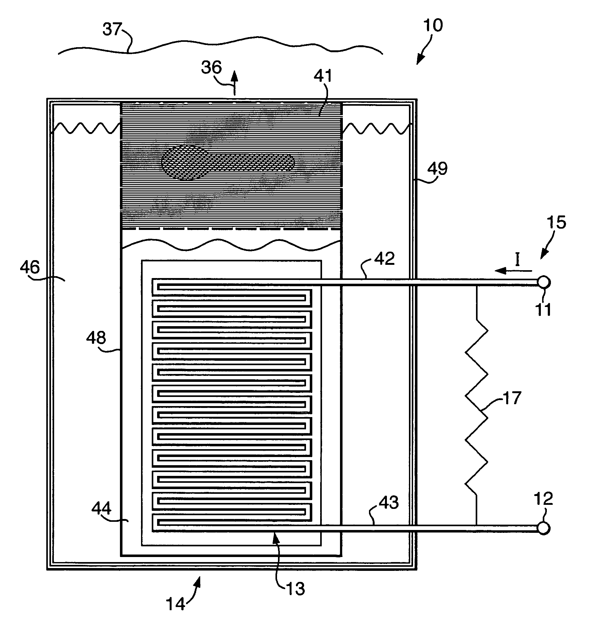
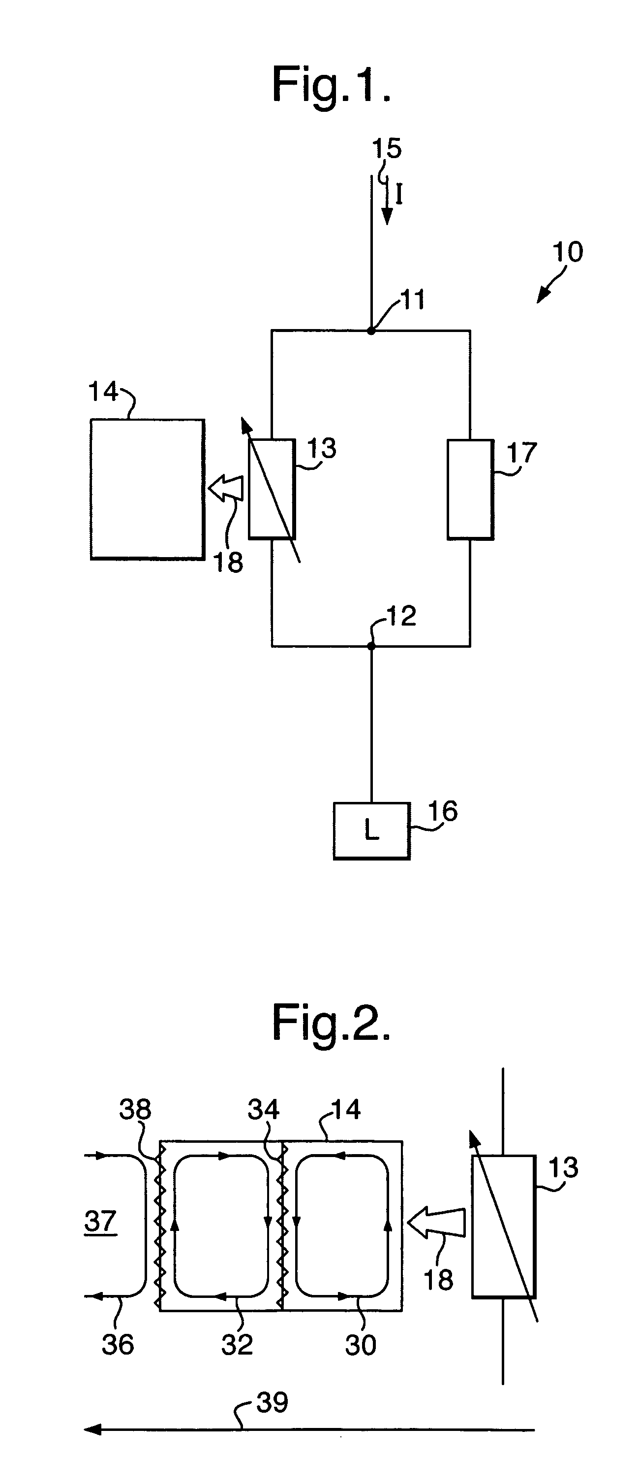
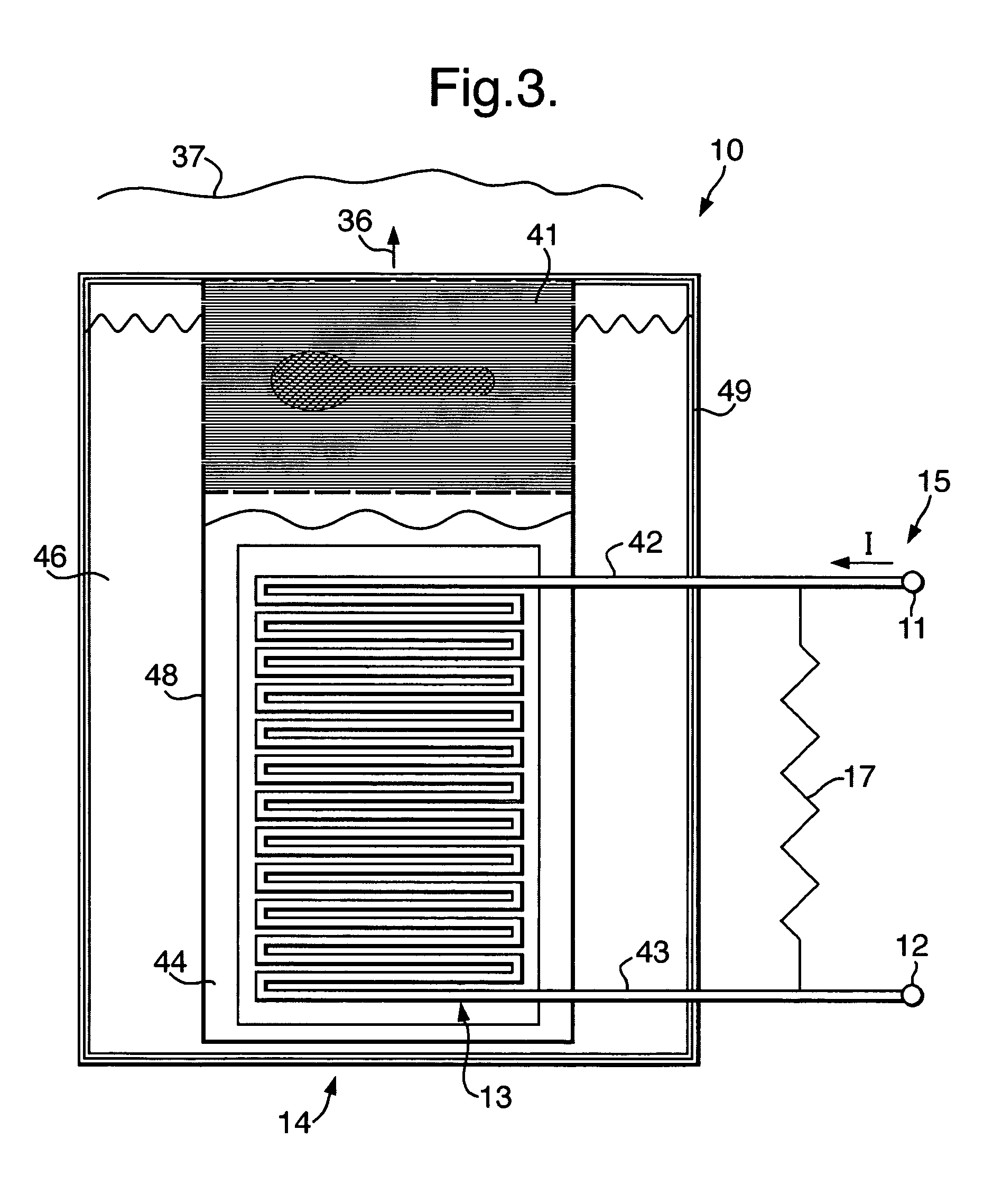
[0023]The figures illustrate a fault current limiter 10 comprising: an input node 11; an output node 12; a variable impedance element 13 coupled between the input node 11 and the output node 12; a multi-cycle refrigeration system 14, comprising a first coolant cycle 30 for cooling 18 the variable impedance element 13 and a second coolant cycle 32, thermally coupled 34 to the first coolant cycle 30, for cooling the first coolant 44, wherein the variable impedance element 13 comprises Magnesium Diboride.

[0024]In more detail, FIG. 1 illustrates a schematic circuit diagram of a fault current limiter 10 for limiting a current I 15 provided to a load 16 when the current I exceeds a threshold value. The fault current limiter 10 comprises a variable impedance element 13, an input node 11, an output node 12, a multi-cycle refrigeration system 14 and a shunt resistor 17. The variable impedance element 13 is electrically connected between the input node 11 and the output node 12. The resistor ...


PUM


Abstract

A fault current limiter comprising: an input node; an output node; a variable impedance element coupled between the input node and the output node; a closed loop cryocooler circuit, comprising a first cryocooler for cooling the variable impedance element and a second cryocooler, thermally coupled to the first cryocooler, for cooling the first coolant, wherein the variable impedance element comprises Magnesium Diboride.

Description

CROSS-REFERENCE TO RELATED APPLICATIONS[0001]This application is a Continuation-In-Part of National Application Number 11 / 294,415, now U.S. Pat. No. 7,444,826, filed Dec. 6, 2005 and currently pending, which is a Continuation of PCT / GB2004 / 002370, filed Jun. 3, 2004. This application also claims foreign priority to GB 0315663.5, filed Jul. 4, 2003.BACKGROUND OF THE INVENTION[0002]Embodiments of the present invention relate to a Fault Current Limiter (FCL). In particular, they relate to an FCL for an electricity distribution network.[0003]Electricity distribution networks are used to transmit electric current from a source to a load. If an electrical fault occurs in such a network, large currents are generated that can cause damage to the load. Fault current limiters vary their impedance when there is a fault and reduce the current.[0004]Superconducting materials have a low impedance superconductive state and a high impedance normal state. They can be used as a variable impedance ele...

Claims


Application Information

Patent Timeline
IPC IPC(8): F25B19/00F25B9/00H02H7/00
CPCH01L39/16F25D19/006H10N60/30
Inventor SARGENT, PHILIP M.MALKIN, PETERSIMMERS, BRIAN E.
Owner ROLLS ROYCE PLC
Why Eureka
Try Eureka