Mri-compatible devices

a technology of compatible devices and antenna components, applied in the direction of magnetic measurement, magnetic variable regulation, instruments, etc., can solve the problems of inability to fine tune the characteristic impedance values of each antenna component that will affect the receive signal profile, poor contrast dependent of passive visualization devices, and inability to accurately predict the characteristics of each antenna component, etc., to achieve low signal loss, high electrical resistance, and high conductive antenna components

Active Publication Date: 2021-08-12
TRANSMURAL SYST LLC
View PDF3 Cites 0 Cited by
  • Summary
  • Abstract
  • Description
  • Claims
  • Application Information

AI Technical Summary

Benefits of technology

[0011]Conventional active MRI devices have highly conductive antenna components and transmission lines to conduct the received RF signal to the MR scanner with minimal signal loss for device visualization purpose. However, these conductive structures also may couple with RF transmit power during MRI scan and RF induced current flows through the device. The blood vessels and tissues surrounding the active MRI devices during interventional procedures have high electrical resistance. When the RF induced current flows from the active device to the surrounding tissues (i.e. from the distal tip of the active device which has the highest current density along the device), resistive heating is then generated at the device-tissue interface, causing a sudden temperature increase that could be dangerous for the patients. Applicant has come to appreciate that this can be addressed by configuring the electrical properties of the devices to match or closely match the impedance of the surrounding anatomy, as reducing the difference in impedances will reduce such resistive heating.
[0012]It is thus one object of the present disclosure to provide RF receiver antenna fabrication methods that permit construction of devices that can be used to visualize all desired locations over the device profile using a single antenna design without altering the mechanical performance of the device, and also to minimize RF induced heating over the device body by altering the characteristic impedance of specific parts of conductive structures in a seamless manner.

Problems solved by technology

Passively-visualized devices have poor contrast dependent on the device orientation relative to the main magnetic field and often create image artifacts much larger than the actual device profile.
Therefore, fine tuning of the characteristic impedance values of each antenna components that will affect the receive signal profile is not practical.

Method used


Image

  • Mri-compatible devices
  • Mri-compatible devices
  • Mri-compatible devices

Examples


Embodiment Construction

[0049]Reference will now be made in detail to the present preferred embodiments of the disclosure, examples of which are illustrated in the accompanying drawings. The methods and corresponding steps of the disclosed embodiments will be described in conjunction with the detailed description of the system.

[0050]The present disclosure provides embodiments of devices that are useful in interventional MRI (so-called “iMRI”) procedures. Applicant has noticed that a variety of attempts have been made in order to make devices, such as surgical instruments and implants more MRI compatible. But, such devices have shortcomings.

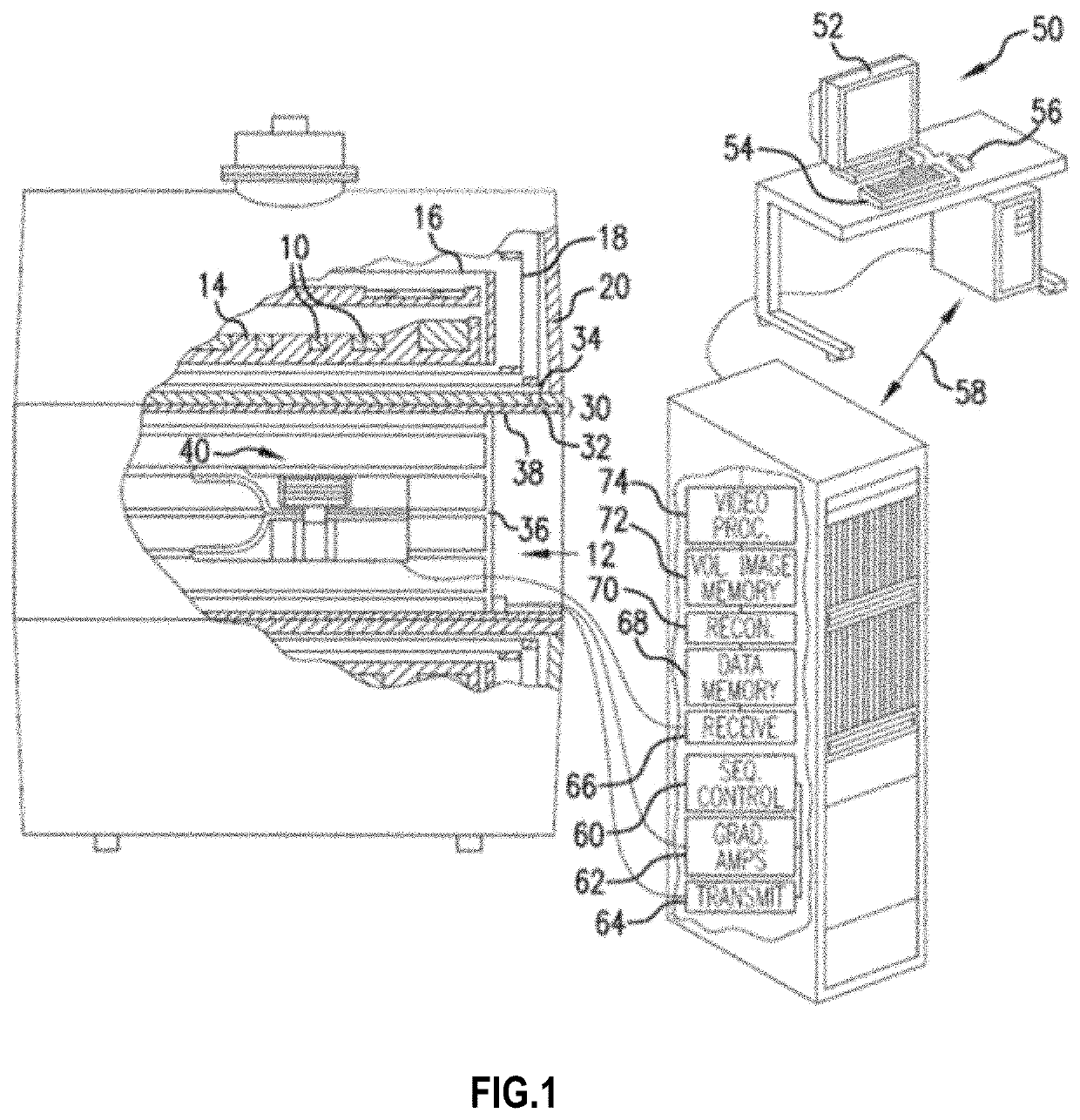
[0051]By way of reference, an exemplary magnetic resonance system is depicted in FIG. 1, and includes a plurality of primary magnetic coils 10 that generate a uniform, temporally constant magnetic field B0 along a longitudinal or z-axis of a central bore 12 of the device. In a preferred superconducting embodiment, the primary magnet coils are supported by a former 14 and...


PUM


Abstract

The present disclosure provides medical devices having MRI-compatible circuitry. Preferably, the devices do not project an enlarged profile, yet their position can be determined during an iMRI procedure. Illustrative embodiments of such a device can include a base surface, a first conducting layer disposed on the base surface, a first insulating layer disposed over at least a portion of the first conducting layer, and a second conducting layer disposed over at least a portion of the first insulating layer.

Description

CROSS-REFERENCE TO RELATED APPLICATION[0001]The present patent application is a continuation-in-part of and claims the benefit of priority to International Application No. PCT / US21 / 28725, filed Apr. 22, 2021, which in turn claims the benefit of priority to U.S. patent application Ser. No. 17 / 234,608, filed Apr. 19, 2021, U.S. Provisional Application No. 63 / 013,977, filed Apr. 22, 2020, and U.S. Provisional Application No. 63 / 170,682, filed Apr. 5, 2021. The present patent application is a continuation in part of and claims the benefit of priority to International Patent Application No. PCT / US2019 / 57297, filed Oct. 21, 2019, which in turn claims the benefit of priority to U.S. Patent Application Ser. No. 62 / 748,026, filed Oct. 19, 2018. Each of the foregoing patent applications is incorporated by reference herein in its entirety for any purpose whatsoever.FIELD[0002]This disclosure relates generally to interventional devices designed to be actively visualized through embedded Radio F...

Claims


Application Information

Patent Timeline
Patent Type & Authority Applications(United States)
IPC IPC(8): G01R33/28G01R33/36
CPCG01R33/287G01R33/36G01R33/34007G01R33/34053G01R33/34069G01R33/341
Inventor KOCATURK, OZGURRAFIEE, NASSER
Owner TRANSMURAL SYST LLC
Why Eureka
Try Eureka