Relay circuitry and switching circuitry for power-over-network devices

a technology of switching circuitry and relay circuitry, which is applied in the direction of data switching networks, contact mechanisms, manufacturing tools, etc., can solve the problems of increasing the amount of required and the added cost of circuitry, and achieves the effect of efficient shutting off the relay circuitry, and reducing the cost of circuitry

Active Publication Date: 2011-03-29
MARVELL ASIA PTE LTD
View PDF30 Cites 0 Cited by
  • Summary
  • Abstract
  • Description
  • Claims
  • Application Information

AI Technical Summary

Benefits of technology

[0005]In accordance with the present invention, an integrated, on-chip relay circuitry and switching circuitry that is used in connection with detecting the presence of power-over-network devices such as POE devices and with subsequently supplying power to those devices is provided. The relay circuitry utilizes the test signals that are transmitted to and received by the power-over-network device to bring the relay circuitry to a closed-switch state with minimal signal loss and relatively little load capacitance. Specifically, the relay circuitry includes circuitry that is configured to store charge when the inputs are of one polarity, and to use the stored charged to drive the relay circuitry to a closed-switch state when the inputs are of the reverse polarity. The switching circuitry is configured to efficiently shut off the relay circuitry when power is supplied to the network device.

Problems solved by technology

One notable disadvantage caused by implementing the relay circuitry off-chip is the added cost of the circuitry due to a relative increase in the amount of required die.

Method used


Image

  • Relay circuitry and switching circuitry for power-over-network devices
  • Relay circuitry and switching circuitry for power-over-network devices
  • Relay circuitry and switching circuitry for power-over-network devices

Examples


Embodiment Construction

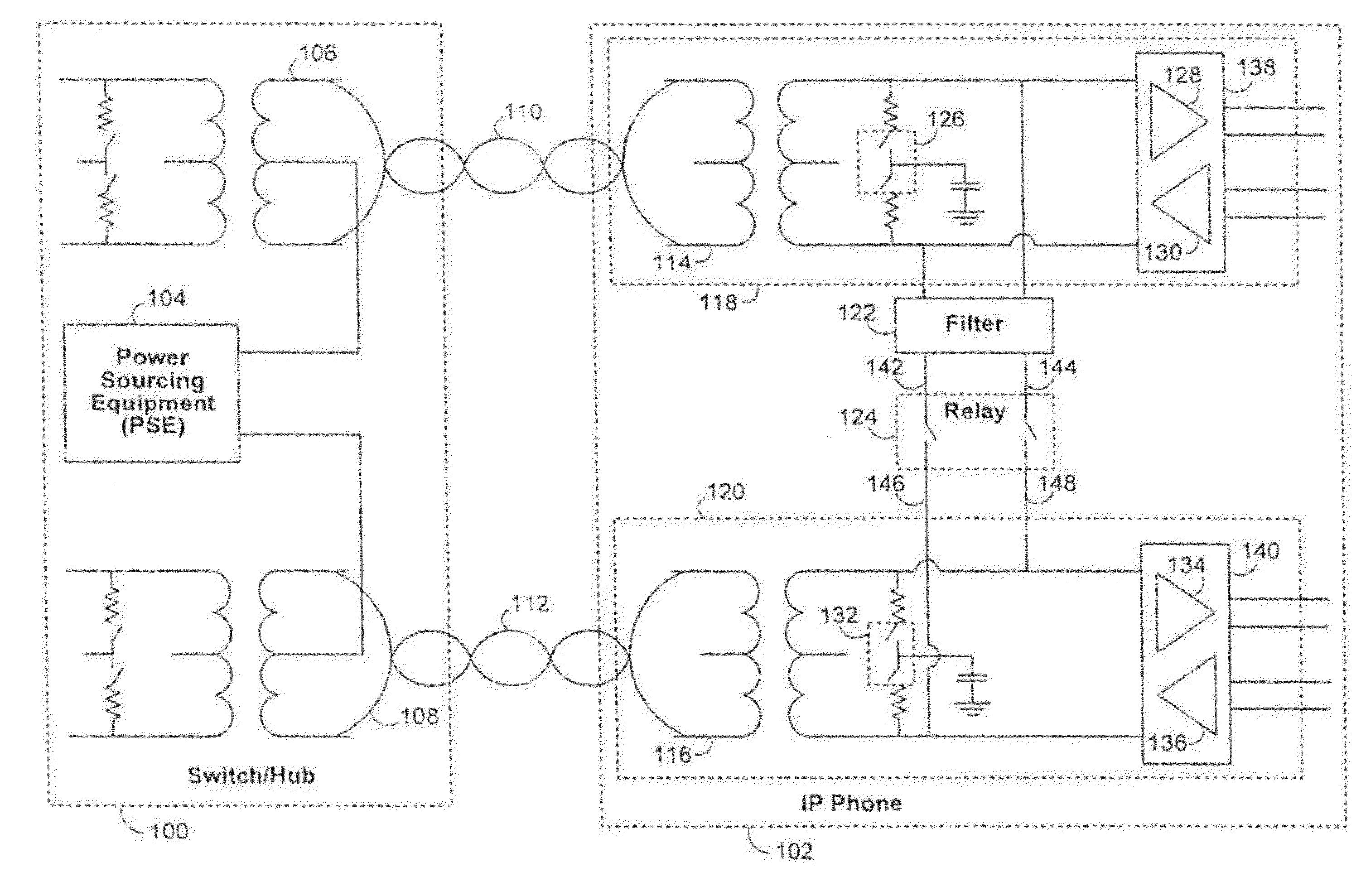
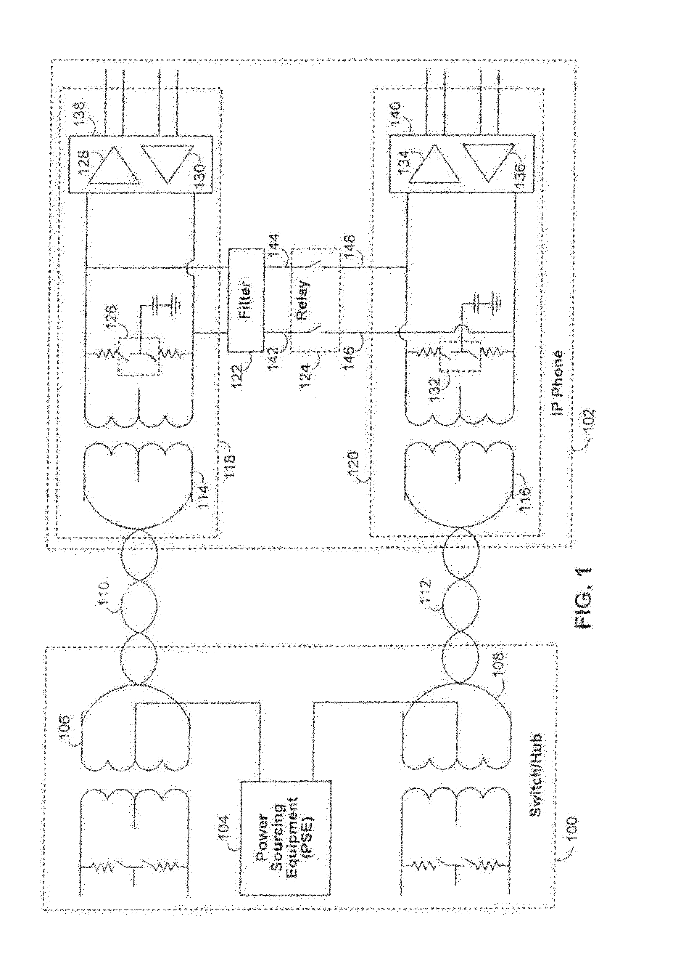
[0012]FIG. 1 shows an illustrative embodiment of a typical system in which the circuitry of the present invention is implemented. In FIG. 1, power-supplying network device 100 (such as a switch or a hub) is connected to an Ethernet network to which power-over-network device 102 (such as an Internet Protocol (“IP”) telephone) is connected. Although references are made herein to an Ethernet network, such references are merely the purpose of illustration, and it will therefore be understood that the present invention may be realized in other suitable types of networks. Specifically, in FIG. 1, power-supplying network device 100 includes power-sourcing equipment (“PSE”) 104 that is connected to the center taps in the primary side of each of power transformers 106 and 108. As a result, the power provided by PSE 104 is supplied over Ethernet links 110 and 112 to the secondary sides of power transformers 114 and 116, which are in turn connected to power-over-network device 102.

[0013]The po...


PUM

PropertyMeasurementUnit
peak-to-peak voltageaaaaaaaaaa
voltageaaaaaaaaaa
voltageaaaaaaaaaa

Abstract

Relay circuitry for a power-over-network device is provided. The relay circuitry allows power-supplying network devices to identify and subsequently to supply power across a network connection to the power-over-network device, thereby eliminating the need for external power sources. The relay circuitry is operative using only the signals transmitted along a data line across the network connection. The relay circuitry is integrated together with switching circuitry on-chip on the power-over-network device. The relay circuitry and switching circuitry are further designed to propagate both the test signals and the subsequent data signals prior to and after the turning on of the power-over-network device, respectively, with minimal signal degradation.

Description

CROSS REFERENCE TO RELATED APPLICATION[0001]This application is a continuation of U.S. patent application Ser. No. 11 / 030,002 filed Jan. 4, 2005, which is incorporated herein by reference in their entirety.BACKGROUND OF THE INVENTION[0002]The present invention relates to circuitry for power-over-network devices, such as power-over-Ethernet (“POE”) devices, that are powered by a network data cable rather than a separate power source. More particularly, the present invention relates to integrated, on-chip relay circuitry for such network devices.[0003]One recent advance with respect to Ethernet network technology has been in the development of power-over-Ethernet devices. As the name suggests, POE devices are powered solely by the Ethernet cable to which they are connected and therefore do not require power from an external AC power source. U.S. patent application Ser. No. 10 / 098,865, filed on Mar. 15, 2002, for example, describes systems and methods for detecting network devices such...

Claims


Application Information

Patent Timeline
Patent Type & Authority Patents(United States)
IPC IPC(8): H01H47/22
CPCH04L12/40045
Inventor ROO, PIERTECHAN, WYANT
Owner MARVELL ASIA PTE LTD
Why Eureka
Try Eureka