Arrangement for enhancing spectral contrast of a VIPA spectrometer

Active Publication Date: 2021-07-13
FOND INST ITAL DI TECH
View PDF11 Cites 0 Cited by
  • Summary
  • Abstract
  • Description
  • Claims
  • Application Information

AI Technical Summary

Benefits of technology

The patent describes a new way to create a spectrometer that can measure the elastic light from a sample. By using a special mask, the researchers can remove most of the unwanted light from the sample, which makes it easier to get accurate measurements. This means that the spectrometer can produce better results with less signal loss and without needing extra components. This technique could be useful for a wide range of applications, like Brillouin microscopy, where it can help quickly acquire mechanical images without needing complex and expensive equipment.

Problems solved by technology

Standard methods for measuring mechanical properties require physical contact with the sample, which makes these techniques invasive and limited to surface topography.
Despite their remarkable spectral resolution and contrast, interferometers and etalon FP typically require a long integration time (>1 sec), which in turn limits Brillouin spectroscopy to single point measurements.
Despite their unmatched throughput efficiency, conventional VIPA spectrometers are naturally limited by a spectral contrast of approximately 30 dB.
This limit is a consequence of an unbalanced amplitude of the output / transmitted beam, which leads to reduced visibility of the fringes.
However, this happens at the expense of a significantly reduced throughput efficiency of ˜25% (in the case of 2 VIPAs), with an associated increase in image acquisition time.
In addition, VIPA multi-stage spectrometers require a large number of optical components, which makes such systems expensive and difficult to align.
However, these schemes result in a high level of losses or have limited contrast gains (˜15 dB).
Other techniques lead to increased extinction by suppressing the elastic background light.
However, these techniques do not increase the effective contrast of the spectrometer.

Method used


Image

  • Arrangement for enhancing spectral contrast of a VIPA spectrometer
  • Arrangement for enhancing spectral contrast of a VIPA spectrometer
  • Arrangement for enhancing spectral contrast of a VIPA spectrometer

Examples


first embodiment

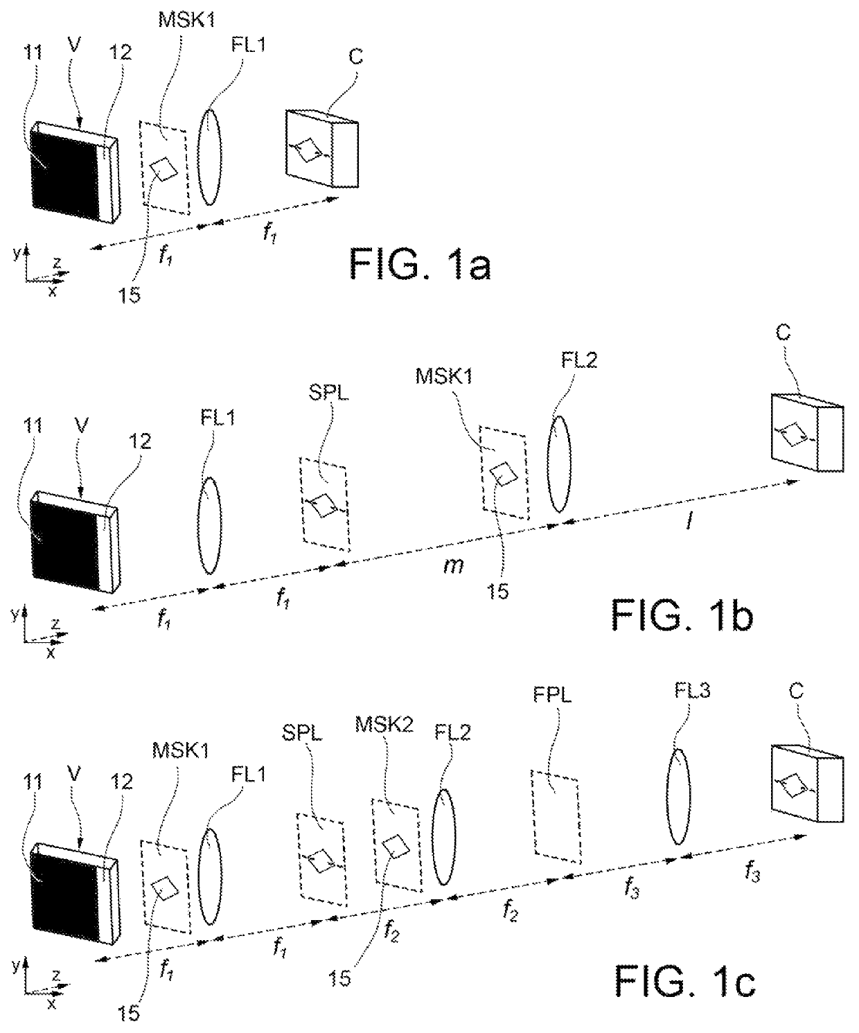
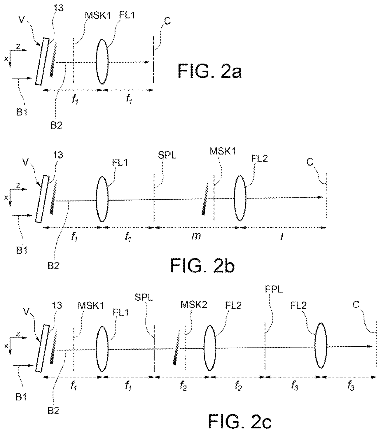
lass="d_n">[0024]With reference to FIGS. 1a and 2a, a spectrometer according to the invention is now described.

[0025]Such a spectrometer comprises a Virtually Imaged Phased Array element (hereinafter, VIPA element), indicated with V in the figures, which is configured to receive an electromagnetic input radiation B1 and to generate an electromagnetic output radiation B2. When the spectrometer is used in a Brillouin microscope apparatus, the input radiation B1 is the radiation that is triggered by a sample illuminated by a laser beam. The optical axis of propagation of the electromagnetic radiation B2 is represented extending parallel to an axis z of a system of Cartesian axes xyz. The VIPA V member is configured in such a way that the spectrum of the output electromagnetic radiation B2 is dispersed along a transverse dispersion axis with respect to the optical propagation axis of the output electromagnetic radiation B2. The VIPA V member is a particular type of Fabry-Perot etalon, c...

third embodiment

[0031]With reference to FIGS. 1c and 2c, a single stage spectrometer VIPA is shown which adopts an additional configuration 4f. Elements corresponding to those of the embodiments in FIGS. 1a-1b and 2a-2b have been indicated with the same reference numerals.

[0032]The spectrometer in FIGS. 1c and 2c comprises a third Fourier lens FL3 with a focal length f3. The additional configuration 4f may be used to arrange a Lyot filter at a Fourier plane (FPL) between the second lens FL2 and the third lens FL3.

[0033]As can also be seen in FIGS. 1c and 2c, there is an additional diffraction mask MSK2. More generally, multiple diffraction masks may be used before or after each Fourier lens. In any case, these diffraction masks must not be arranged at the spectral plane SPL where diffraction would not take place.

[0034]With reference to FIG. 10, the operating principle of the present invention is further explained. At the output of the VIPA, beams B1′ and B1″ with different wavelengths coincide. How...


PUM


Abstract

A spectrometer is provided which comprises a Virtually Imaged Phased Array member configured to receive an electromagnetic input radiation and to generate an electromagnetic output radiation, in which a spectrum of the electromagnetic output radiation is dispersed along a dispersion axis (x) transverse to an optical axis (z) of propagation of the electromagnetic output radiation; a Fourier lens adapted to convert the output electromagnetic radiation into a spectral pattern; an image sensor adapted to detect the spectral pattern; and at least one diffraction mask arranged along the optical axis (z) for propagating the output electromagnetic radiation, in a position not coincident with a spectral plane of the spectrometer. Through the diffraction mask, which comprises a material blocking the transmission of the output electromagnetic radiation, an aperture is obtained which allows the transmission of the output electromagnetic radiation, and whose edge comprises at least one inclined segment.

Description

CROSS-REFERENCE TO RELATED APPLICATIONS[0001]This application is a U.S. National Phase filing of PCT International Patent Application No. PCT / IB2018 / 056829, having an international filing date of Sep. 7, 2018, which claims priority to Italian Patent Application No. 102017000109143, filed Sep. 29, 2017 each of which is hereby incorporated by reference in its entirety.FIELD OF THE INVENTION[0002]The present invention relates to Brillouin spectroscopy and microscopy techniques.BACKGROUND OF THE INVENTION[0003]Brillouin microscopy is an emerging imaging technique that combines confocal microscopy (or other microscopy) and Brillouin spectroscopy to optically measure the mechanical properties of matter.[0004]Brillouin light scattering is an anelastic scattering process that arises from the interaction of light with intrinsic spontaneous acoustic waves (acoustic phonons) of matter. The light elastically diffused (Rayleigh) by a biological system has the same frequency as the lighting light...

Claims


Application Information

Patent Timeline
IPC IPC(8): G01J3/44G01J3/02G01J3/26
CPCG01J3/4412G01J3/0208G01J3/0229G01J3/26
Inventor ANTONACCI, GIUSEPPE
Owner FOND INST ITAL DI TECH
Why Eureka
Try Eureka