Receiver

a receiver and receiver technology, applied in the field of receivers, can solve the problems of limiting the bandwidth at the input of the receiver, limiting the usability of the receiver, etc., and achieve the effect of minimal signal loss

Active Publication Date: 2019-04-09
INNOVATIONSZENTRUM FUER TELEKOMMUNIKATIONSTECHNIK GMBH IZT
View PDF11 Cites 0 Cited by
  • Summary
  • Abstract
  • Description
  • Claims
  • Application Information

AI Technical Summary

Benefits of technology

[0013]Embodiments of the present invention are based on the finding that intermodulation products (in particular of second order) at the receiver input can be reduced effectively by means of selecting a sufficiently narrow filter or a plurality of sufficiently narrow filters arranged to form a filter unit. In order to make use of this effect for the entire filter width, the individual narrow-band filters are connected to form a filter unit or to form two filter banks such that the plurality of filters covers the entire frequency band to be digitalized as far as possible. Due to the fact that each filter is coupled directly to an AD converter, digitalization is performed per sub-frequency band so that, subsequently, the individual sub-bands can be merged again in a digital signal processing stage with no losses to form an overall signal. Consequently, very good IP2 values, which evaluate the resulting second-order intermodulation products, can be achieved on the one hand. Secondly, the signal losses are minimal, since there are no losses, in particular when merging.
[0018]It is to be mentioned here that, in accordance with embodiments, the filters are implemented to be purely passive elements. In accordance with embodiments, the plurality of filters or the two filter banks here can be connected to the signal source, like, for example, the antenna, or, generally, an input, via a common power divider. Such filter bands may be realized at low introduction attenuation and reactive power dividers (attenuation factor <3 dB). It is of advantage here that active elements upstream of the filters, for example, may be dispensed with completely. Electronic switches may also be omitted. Due to these measures, the IP2 values can be improved further. Another advantage is that the sensor is well protected from excess voltages by means of the passive filter network. It is to be mentioned here also that the passive filters for the filter unit keep the complexity thereof very small, in particular when compared to switchable or running pre-selection.

Problems solved by technology

Typically, this means a limitation of the bandwidth at the input of the receiver.
This restricts the usability of the receiver considerably.

Method used


Image

  • Receiver
  • Receiver
  • Receiver

Examples


Embodiment Construction

[0026]Before discussing below in greater detail embodiments of the present invention referring to the appended drawings, it is to be pointed out that equal elements or structures are provided with equal reference numerals so that the description thereof is mutually applicable or exchangeable.

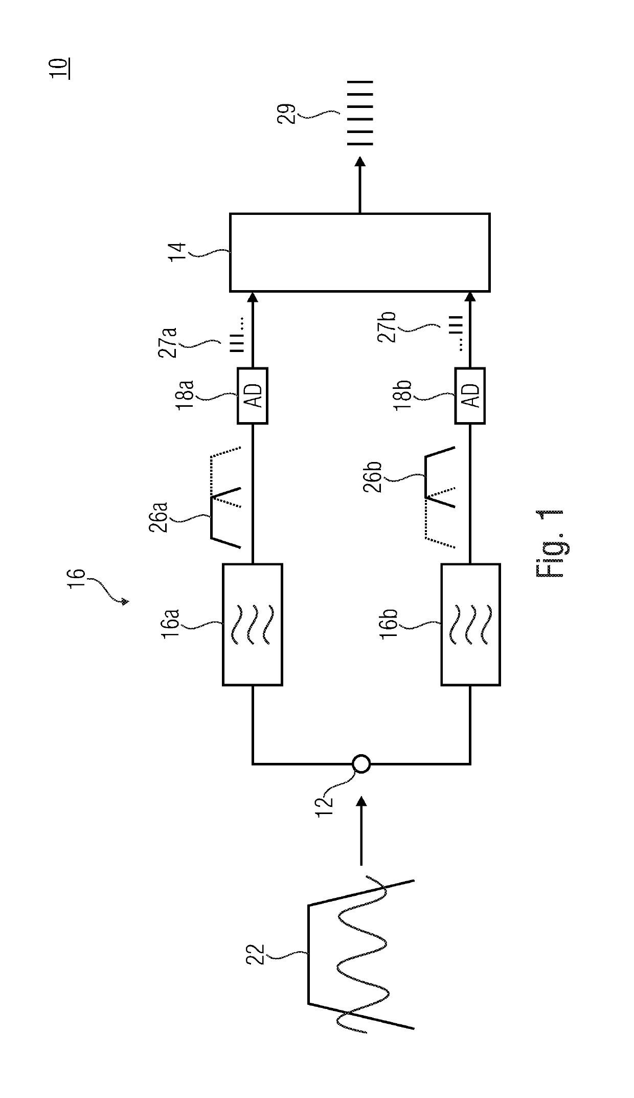
[0027]FIG. 1 shows a receiver 10, like a radio receiver, comprising a common input 12, digital signal processing 14 which here represents the output of the receiver. In this embodiment, two signal paths, characterized by letters a and b, are provided between the input 12 which may exemplarily be an antenna or, generally, a signal input or coupled to an antenna, and the digital signal processing 14.

[0028]Every signal path a and b comprises a filter 16a and 16b, respectively, like an analog filter 16a and 16b, and an analog-to-digital converter 18a and 18b, respectively. The filters 16a and 16b together form the filter unit 16. All the filters 16a and 16 of the filter unit 16 are connected to the ...


PUM


Abstract

A receiver for receiving an analog signal having a frequency band to be digitalized has a filter unit having at least two filters for at least two receive paths, an AD converter per receive path, and digital signal processing. The filters are coupled to a common signal source in order to obtain the analog signal having the frequency band to be digitalized, and configured to divide the frequency band to be digitalized into at least two sub-bands for the at least two receive paths. The analog-to-digital converters are configured to digitalize the signals of the at least two sub-frequency bands. The digital signal processing is coupled to the at least two analog-to-digital converters in order to obtain the at least two digitalized signals and merge the at least two signals to be digitalized. The at least two filters, with regard to their filter characteristics, are configured such that the at least two sub-frequency bands have a relative bandwidth of <1:2.

Description

CROSS-REFERENCE TO RELATED APPLICATIONS[0001]This application is a continuation of copending International Application No. PCT / EP2016 / 073798, filed Oct. 5, 2016, which is incorporated herein by reference in its entirety, and additionally claims priority from German Application No. 10 2015 219 739.5, filed Oct. 12, 2015, which is also incorporated herein by reference in its entirety.BACKGROUND OF THE INVENTION[0002]Embodiments of the present invention relate to a receiver for receiving an analog signal, like a high-frequency signal, having a frequency band to be digitalized.[0003]Such a receiver may, for example, be employed as a radio receiver or measuring receiver, in particular when radio or measuring signals are to be detected in high quality over a relatively high bandwidth. In a frequency range having a great frequency width, like in the frequency range below 30 MHz, high powers may occur at the antenna output, in particular with large receive antennas, depending on the conditi...

Claims


Application Information

Patent Timeline
Patent Type & Authority Patents(United States)
IPC IPC(8): H04B1/10H04B1/00H03M1/12H04L27/26
CPCH04B1/1036H03M1/121H04L27/2649H04B1/0057H04B2001/1054
Inventor PERTHOLD, RAINER
Owner INNOVATIONSZENTRUM FUER TELEKOMMUNIKATIONSTECHNIK GMBH IZT
Why Eureka
Try Eureka