
Method and apparatus for grid project modeling language

Inactive Publication Date: 2007-05-24
IBM CORP
View PDF36 Cites 71 Cited by
  • Summary
  • Abstract
  • Description
  • Claims
  • Application Information

AI Technical Summary

Problems solved by technology

Among these services, the resource management and scheduling tends to be the most challenging to perform optimally.
Because known grid computing systems only take into consideration processor load(s) as a dynamic factor for determining scheduling of jobs, and fail to consider network traffic that the grid jobs may create, sub-optimal scheduling often results.
As a result, the grid jobs, which are intended to be performed in an unobtrusive manner with regard to the regular functioning of the nodes, may adversely affect the existing loads on the nodes.
Because of this sub-optimal scheduling that results due to using only the processor load(s) as a basis for the scheduling, many scientific and commercial enterprises are reluctant to make use of grid computing because of the possible negative impact it may cause on their existing information technology infrastructures.
First, these enterprises are uncertain about how much grid activity may disrupt their existing workload; second, they are hesitant to use the computing grid for mission critical projects because they are unable to quantify the capacity of their grid that is necessary to run the grid jobs associated with the grid project within a required time span.
These problems with existing grid computing systems are rooted in the fact that resource management and scheduling in these grid computing systems do not take into account the necessary amount of network traffic for performing grid jobs or the affect that this traffic may have on existing loads of nodes in the grid.
Network traffic may negatively affect both the performance of the existing workloads on the nodes in a grid as well as the performance of the grid jobs themselves.

Method used


Image

  • Method and apparatus for grid project modeling language
  • Method and apparatus for grid project modeling language
  • Method and apparatus for grid project modeling language

Examples


Embodiment Construction

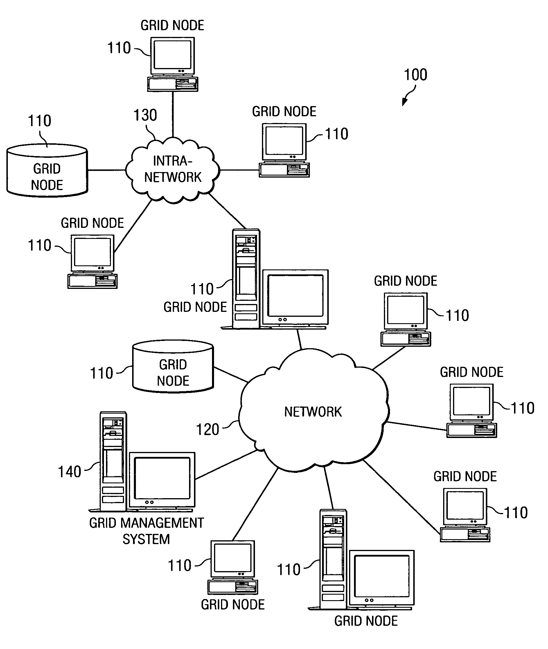
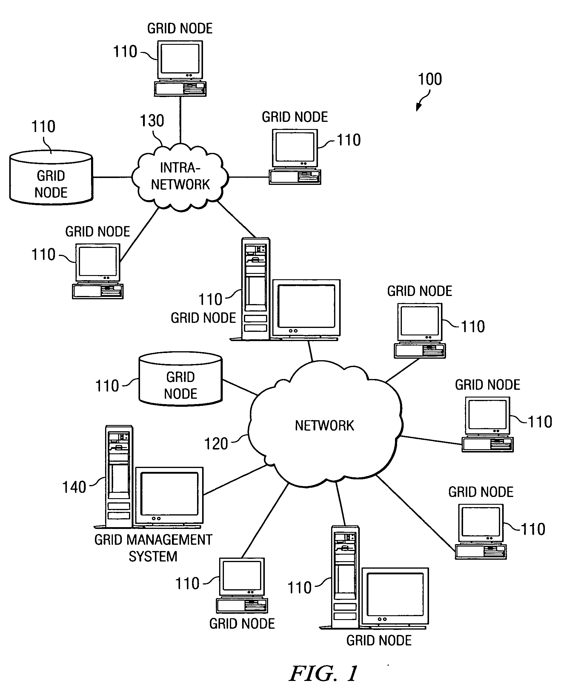
[0029]FIG. 1 is an exemplary diagram of a computing grid environment in which aspects of the present invention may be implemented. As shown in FIG. 1, the computing grid 100 includes a plurality of grid nodes 110 coupled together via one or more networks 120-130. The grid nodes may be any type of computing device that is capable of either processing grid jobs and grid data provided to it or is capable of providing such grid data to other grid nodes. For example, a grid node 110 may be a server computing device, client computing device, workstation, personal computer, database system, mainframe computer system, or the like.

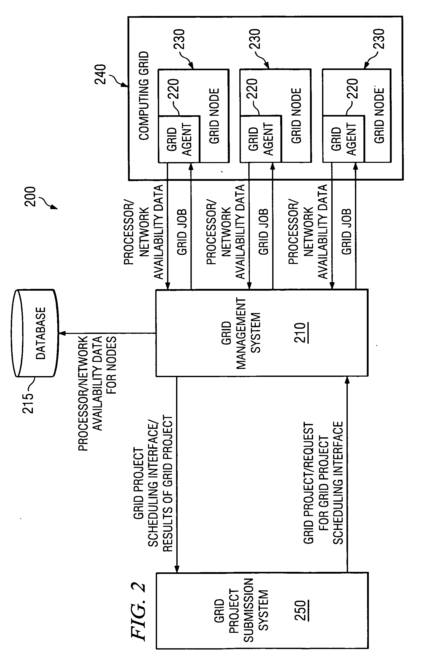
[0030] The computing grid 100 is managed by the grid management system 140. The grid management system 140 communicates with agent software present on the grid nodes 110 to obtain information about each of the grid nodes 110 and to submit grid jobs and grid data to the grid nodes 110 for processing. The grid management system 140 provides the necessary functionali...


PUM


Abstract

A method and apparatus for modeling grid projects, such that their network and node resources may be readily determinable for simulation, scheduling, and control purposes. A model of a grid project is generated using a standardized grid project modeling language that sets forth a sequence of grid project phases. Within each phase, there may be any number of descriptions of parallel activities that need to be performed, such as, CPU processing, network activity, both, or even nested “sub” phases. Each of the descriptions specifies the properties of the described activities, such as the quantity of CPU required, network traffic expected, prerequisites, dependencies, activity splitting limits and characteristics, reliability actions, etc. The grid project model is parseable by the present invention to determine the various phases of a grid project and the various characteristics of each phase.

Description

BACKGROUND OF THE INVENTION [0001] 1. Field of the Invention [0002] The present invention is generally directed to an improved data processing system. In particular, the present invention is directed to an improved grid computing system in which a representation of a grid project is generated in accordance with a standardized modeling language. [0003] 2. Description of the Related Art [0004] In the 1990's, computer scientists began exploring the design and development of a computer infrastructure, referred to as the computation grid, whose design was based on the electrical power grids that had been known to date. Grid computing was initially designed for use with large-scale, resource intensive scientific applications, such as the Search for Extraterrestrial Intelligence (SETI) program's computing grid, that require more resources than a small number of computing devices can provide in a single administrative domain. Since then, grid computing has become more prevalent as it has in...

Claims


Application Information

Patent Timeline
IPC IPC(8): G06F9/46
CPCG06F9/5072
Inventor BERSTIS, VIKTORSHARPER, ELLEN KAYLEONARD, BRIAN E.PRESTENBACK, KYLE JOSEPH
Owner IBM CORP
Learn More