Eureka AIR delivers breakthrough ideas for toughest innovation challenges, trusted by R&D personnel around the world.

Quick EGR flow restriction test based on compensated mass flow differential

Active Publication Date: 2007-05-31
GM GLOBAL TECH OPERATIONS LLC
View PDF5 Cites 8 Cited by
  • Summary
  • Abstract
  • Description
  • Claims
  • Application Information

AI Technical Summary

Benefits of technology

[0005] Accordingly, the present invention provides an engine control system that monitors flow restriction through an exhaust gas recirculation (EGR) system of an engine. The engine control system includes a first module that calculates a test EGR mass flow ra

Problems solved by technology

EGR involves re-circulating exhaust gases back into the cylinders, which limits the amount of oxygen available for combustion and lowers cylinder temperatures.
However, debris build-up within the EGR system restricts exhaust flow therethrough and minimizes the effectiveness of the EGR system.
This method provides distinct disadvantages in that the MAP difference can have high variation under different engine operating conditions and it is difficult to calibrate compensation factors for the various engine operating conditions.

Method used


Image

  • Quick EGR flow restriction test based on compensated mass flow differential
  • Quick EGR flow restriction test based on compensated mass flow differential
  • Quick EGR flow restriction test based on compensated mass flow differential

Examples


Embodiment Construction

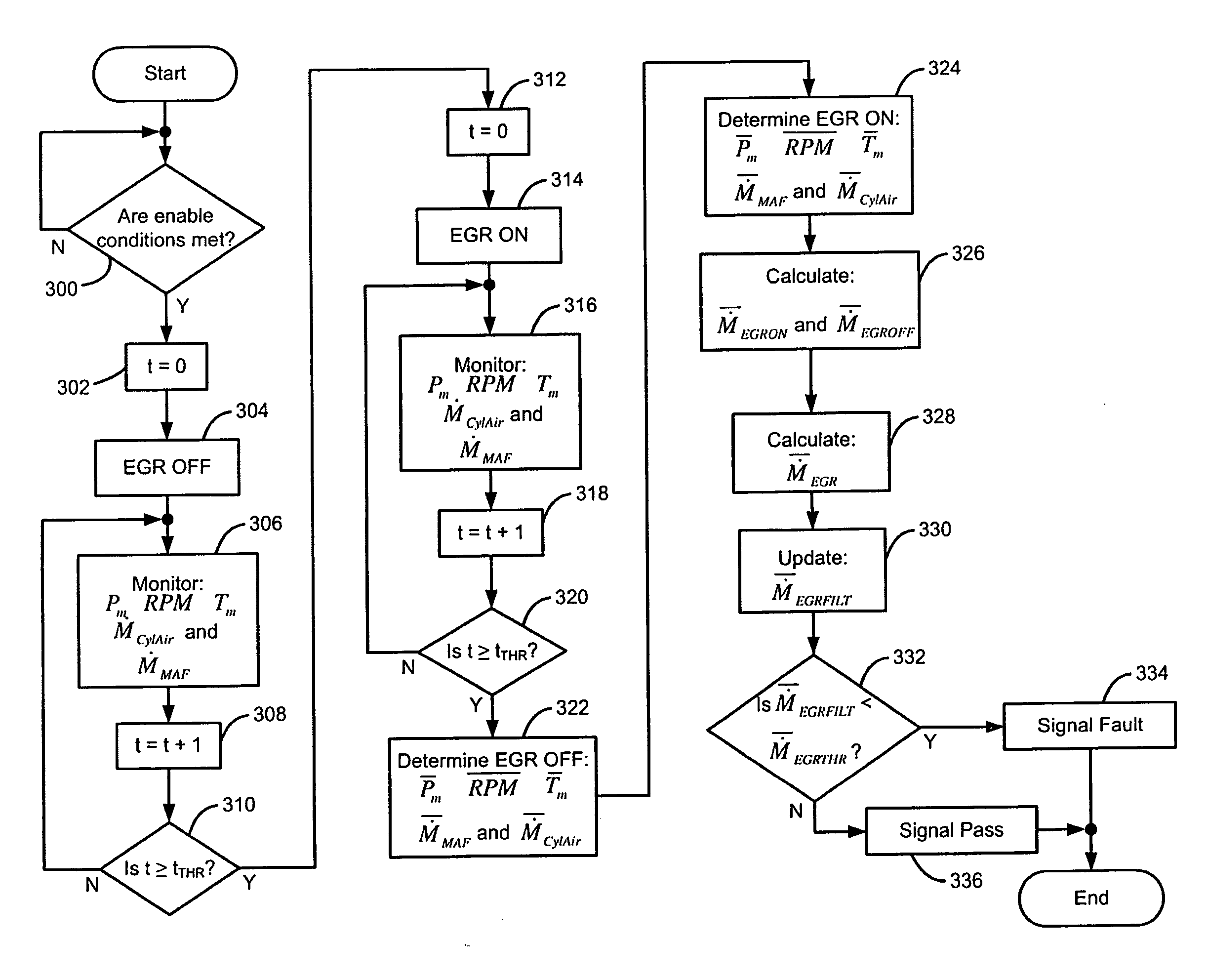
[0016] The following description of the preferred embodiment is merely exemplary in nature and is in no way intended to limit the invention, its application, or uses. For purposes of clarity, the same reference numbers will be used in the drawings to identify similar elements. As used herein, the term module refers to an application specific integrated circuit (ASIC), an electronic circuit, a processor (shared, dedicated, or group) and memory that execute one or more software or firmware programs, a combinational logic circuit, and / or other suitable components that provide the described functionality.

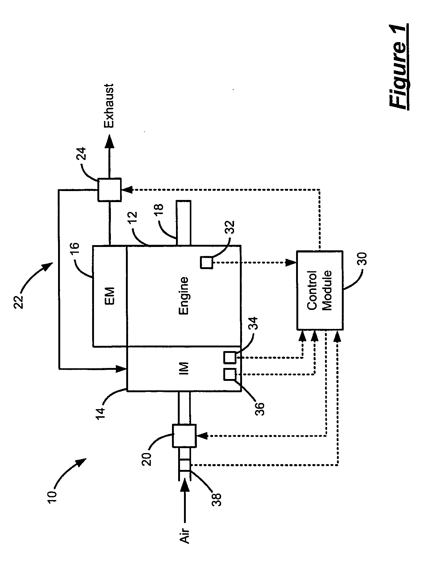
[0017] Referring now to FIG. 1, an exemplary engine system 10 is illustrated. The engine system 10 includes an engine 12, an intake manifold 14 and an exhaust manifold 16. The engine 12 combusts an air and fuel mixture within cylinders (not shown) to drive pistons (not shown) that rotatably drive a crankshaft 18. Air is drawn through a throttle 20 and into the intake manifold 14, which...


PUM


Abstract

An engine control system that monitors flow restriction through an exhaust gas recirculation (EGR) system of an engine includes a first module that calculates a test EGR mass flow rate based on a first average EGR mass flow rate when the EGR system is in an EGR OFF mode and a second average EGR mass flow rate when the EGR system is in an EGR ON mode. A second module selectively generates a fault signal based on the test EGR mass flow rate.

Description

FIELD OF THE INVENTION [0001] The present invention relates to exhaust gas recirculation (EGR) systems for internal combustion engines, and more particularly to a flow restriction test for an EGR system. BACKGROUND OF THE INVENTION [0002] Internal combustion engines combust an air and fuel mixture within cylinders to reciprocally drive pistons within the cylinders. The pistons rotatably drive a crankshaft to provide drive torque to a powertrain. Exhaust generated by the combustion process is exhausted from the engine through an exhaust manifold, is treated in an exhaust system and is released to atmosphere. [0003] Engine systems often include an exhaust gas recirculation (EGR) system to reduce engine emissions. EGR involves re-circulating exhaust gases back into the cylinders, which limits the amount of oxygen available for combustion and lowers cylinder temperatures. EGR enables ignition timing to remain at an optimum point, which improves fuel economy and / or performance. However, ...

Claims


Application Information

Patent Timeline
IPC IPC(8): F02M25/07F02B47/08G01M19/00G06F17/00G01M99/00
CPCF02D41/0055F02D41/0072F02D41/187F02D2200/0406F02D2200/0414F02M25/0702Y02T10/47F02M26/49Y02T10/40
Inventor WANG, WENBOMCLAIN, KURT
Owner GM GLOBAL TECH OPERATIONS LLC
Why Eureka
Eureka Blog
Learn More