Pushbutton mechanism for keyboards

Inactive Publication Date: 2007-05-31
ZIPPY TECH
View PDF10 Cites 17 Cited by
  • Summary
  • Abstract
  • Description
  • Claims
  • Application Information

AI Technical Summary

Benefits of technology

[0006] Therefore the primary object of the present invention is to solve the aforesaid disadvantages. The present invention provides a bridge structure that has the advantages of the conventional bridge and also includes an axle turning relationship and a positioning harness relationship. According to the bridge of the invention, the inner and outer frames have stub shafts and pivot portions on the side brackets that correspond to each other and form a relative turning relationship. The side brackets also have harness recesses and harness bosses corresponding to each other at a lifting position and a lowering position of the pushbutton in normal conditions. Thereby the bridge can be turned steadily and confine the pushbutton stroke.
[0007] Another object of the invention is to provide a bridge with the harness recess and harness boss coupled in a direction same as the coupling juncture of the stub shaft. The harness boss is extended from the side bracket of the inner frame at a length greater than the depth of the harness recess on the side bracket of the outer frame. Hence a gap is formed between the inner frame and the outer frame to prevent contact friction between them to avoid wearing or fracturing.

Problems solved by technology

But the inner and outer frames are difficult to fabricate and couple together.
However, the straddle coupling does not provide a desired positioning harness.
The aforesaid conventional techniques have a common problem, namely when the inner and outer frames of the bridge are coupled together, they have to maintain a constant allowance in normal conditions during turning relative to each other to avoid contact friction between them so that wearing or fracturing can be prevented.
But the present techniques of the bridge do not provide a harness mechanism for the inner and outer frames.
The inner and outer frames could have transverse movements and result in damages.

Method used


Image

  • Pushbutton mechanism for keyboards
  • Pushbutton mechanism for keyboards
  • Pushbutton mechanism for keyboards

Examples


Embodiment Construction

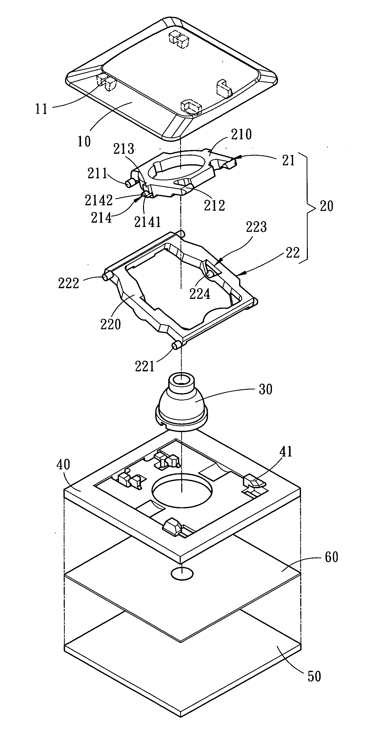
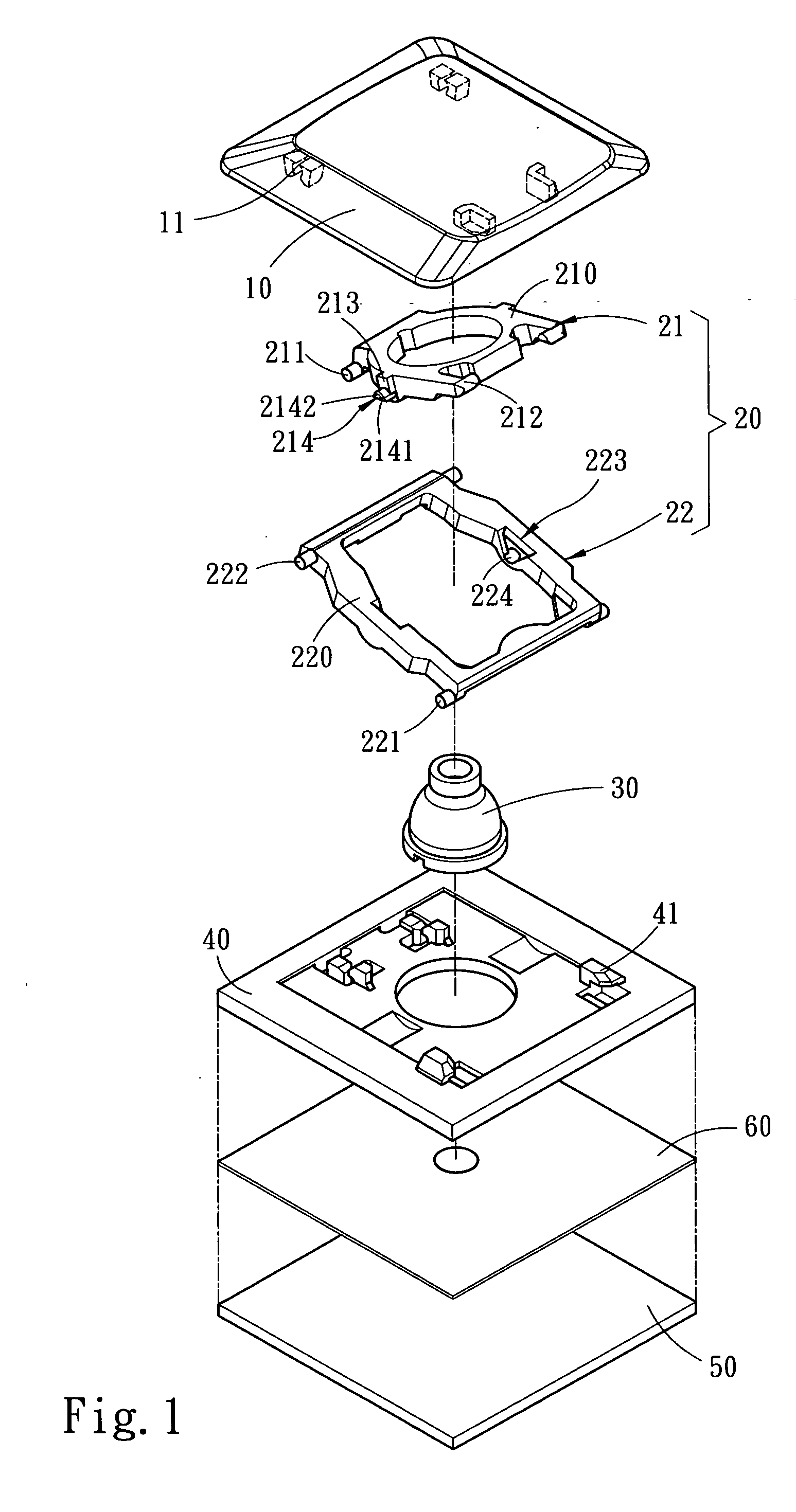
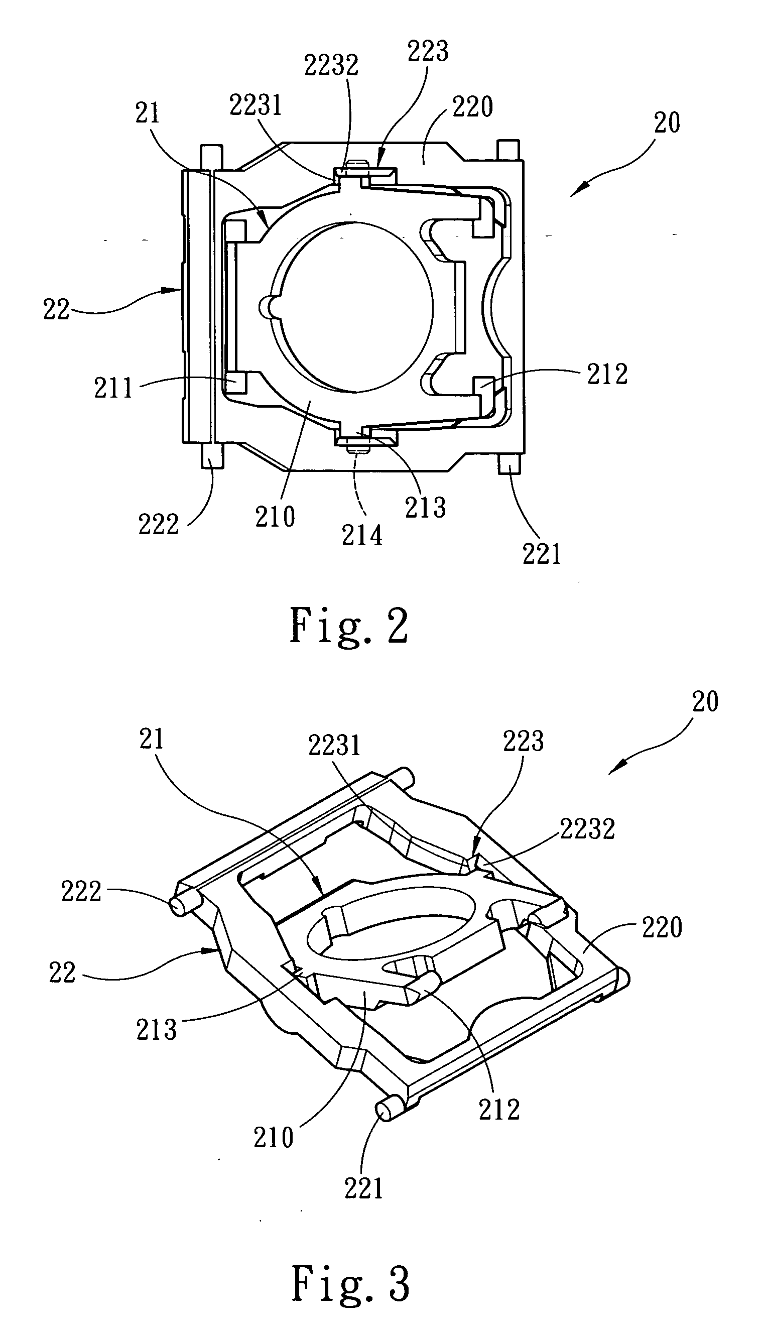
[0015] Please referring to FIGS. 1, 2 and 3, the pushbutton mechanism for keyboards according to the invention includes a bridge 20 that has an inner frame 21 and an outer frame 22 intersected and coupled together. The bridge 20 has one end coupling with a key cap 10 and another end coupling with a base plate 50. The key cap 10 and the base plate 50 are interposed by a signal triggering means. The inner end surface of the key cap 10, the inner and outer frames 21 and 22, and the base plate 50 have respectively coupling elements 11, 211, 212, 221, 222, and 41 that are coupled with one another to allow the bridge 20 to move upwards and downwards. According the existing techniques, a bridge board 40 may also be provided above the base plate 50. The coupling element 41 of the bridge 20 is located on the bridge board 40. The signal triggering means includes an elastic member 30 and a circuit board 60. If only the base plate 50 is adopted, the circuit board 60 is located between the base ...


PUM


Abstract

A pushbutton mechanism for keyboards includes a bridge in a pushbutton that has an inner frame and an outer frame to make the pushbutton movable up and down. The inner frame and outer frame are intersected and coupled together, and have respectively inner side brackets and outer side brackets that have a stub shaft and a pivot portion to form a relative turning relationship. The inner and outer side brackets have respectively harness bosses and harness recesses corresponding to each other to allow the pushbutton to form a lifting position and a lower position in normal conditions. The bridge thus formed can generate a steadier relative turning and confine the stroke distance for the pushbutton.

Description

FIELD OF THE INVENTION [0001] The present invention relates to a pushbutton mechanism for keyboards and particularly to a pushbutton mechanism that has a bridge interposed between a key cap and a base plate to provide a steady relative turning and confine the pushbutton stroke. BACKGROUND OF THE INVENTION [0002] The conventional pushbutton mechanism for thin keyboards mainly includes a bridge (or called scissors-type moving mechanism), a circuit board, an actuation means and a base plate (some also have the bridge mounting onto a bridge board, and have the circuit board interposed between the bridge board and the base plate). The techniques of the bridge mechanism can be divided into two types, each has its benefits and drawbacks as discussed below: [0003] 1. U.S. Pat. Nos. 5,278,374, 5,555,971, 5,964,341 and 6,428,223 propose a bridge that has an inner frame and an outer frame with corresponding stub shafts and pivot portions on the side brackets. The inner frame and outer frame ar...

Claims


Application Information

Patent Timeline
IPC IPC(8): H01H9/00
CPCH01H3/125
Inventor LU, TIEN-MIN
Owner ZIPPY TECH
Why Eureka
Try Eureka