

Bearing system
A bearing and shaft center technology, applied in the field of bearing systems, can solve the problems of increasing the friction coefficient between the shaft sleeve and the shaft center, reducing the service life of the shaft sleeve bearing, and the loss of lubricating oil, so as to prolong the service life, avoid contact friction, reduce friction and reduce friction. The effect of small noise
- Summary
- Abstract
- Description
- Claims
- Application Information
AI Technical Summary
Problems solved by technology
Method used
Image

Examples
Embodiment Construction
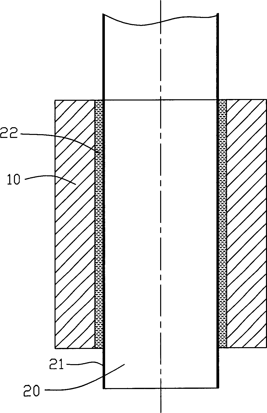
[0010] see figure 1 , the bearing system of the present invention includes a relatively rotatable bushing 10 , a shaft 20 and a lubricating layer 22 between the bushing 10 and the shaft 20 .
[0011] The bushing 10 is installed in a machine body (not shown), and a desired rotating object (not shown), such as a fan blade, is installed on the shaft center 20, so that the fan blade can rotate around the machine body. The shaft sleeve 10 is made of high-hardness materials, such as ceramics, metals, alloys, and the like.
[0012] The shaft 20 can be made of a material that is easy to handle on the surface, such as stainless steel. The shaft 20 is covered with a nano-coating 21 on its surface through surface treatment. The material of the nano-coating 21 can be nano-titanium nitride (TiN), Diamond-like carbon (DLC), nano-titanium aluminum nitride (TiAlN), nano-titanium carbonitride (TiCN), nano-chromium nitride (CrN), nano-tungsten carbide (WC), etc., the lubricating layer 22 is ad...
PUM
 Abstract
Description
Claims
Application Information