
Slewing bearing structure, rotary table and operation machine

A technology of slewing bearings and slewing shafts, applied in mechanical equipment, bearings, magnetic bearings, etc., can solve problems such as high slewing power consumption, high slewing noise, and difficulty in maintenance, and achieve reduced frictional resistance torque, lower slewing noise, and improved life Effect

Active Publication Date: 2021-08-31
SANY AUTOMOBILE HOISTING MACHINERY
View PDF0 Cites 3 Cited by
  • Summary
  • Abstract
  • Description
  • Claims
  • Application Information

AI Technical Summary

Problems solved by technology

[0005] The invention provides a slewing support structure, a slewing table and an operating machine, which are used to solve the problems of large slewing power consumption, large slewing noise, easy damage and difficult maintenance in the existing slewing bearings

Method used


Image

  • Slewing bearing structure, rotary table and operation machine
  • Slewing bearing structure, rotary table and operation machine
  • Slewing bearing structure, rotary table and operation machine

Examples


Embodiment Construction

[0030] In order to make the purpose, technical solutions and advantages of the present invention clearer, the technical solutions in the present invention will be clearly and completely described below in conjunction with the accompanying drawings in the present invention. Obviously, the described embodiments are part of the embodiments of the present invention , but not all examples. Based on the embodiments of the present invention, all other embodiments obtained by persons of ordinary skill in the art without creative efforts fall within the protection scope of the present invention.

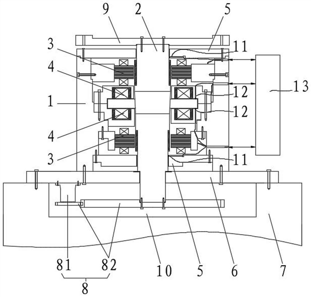
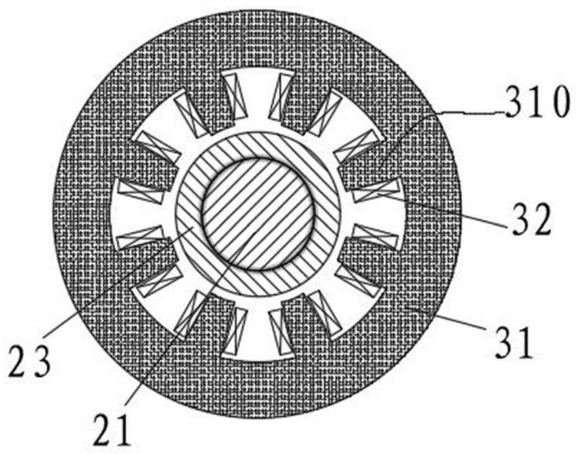
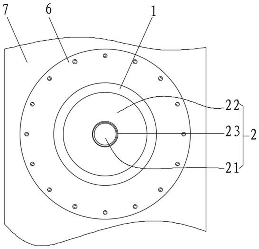
[0031] Combine below Figure 1-Figure 4 A slewing bearing structure, a slewing table and a working machine of the present invention are described.

[0032] Such as Figure 1 to Figure 4 As shown, this embodiment provides a slewing support structure, including a housing 1, a rotary shaft assembly 2, a radial bearing 3 and an axial bearing 4; the rotary shaft assembly 2 is arranged on the hou...


PUM


Abstract

The invention provides a slewing bearing structure, a rotary table and an operation machine. The slewing bearing structure comprises a shell, a rotary shaft assembly, a radial bearing and an axial bearing. The rotary shaft assembly is arranged in the shell in the vertical direction of the shell. The radial bearing is arranged in the shell, coaxially sleeves a main shaft of the rotary shaft assembly and exerts a first acting force in the radial direction on the main shaft, so that the rotary shaft assembly and the radial bearing have the same axis. The axial bearing is arranged in the shell, coaxially sleeves the main shaft and arranged opposite to a thrust disc of the rotary shaft assembly in the axial direction. The axial bearing applies a second acting force which is upward in the axial direction to the thrust disc, so that the rotary shaft assembly is kept in a suspension state in the axial direction. According to the slewing bearing structure, the rotary table and the operation machine, contact friction between movable and static parts of the slewing bearing structure can be avoided, the frictional resistance moment is reduced, the power consumption and slewing noise of the slewing bearing structure are reduced, the service life of the slewing bearing structure is prolonged, and the maintenance-free performance of the slewing bearing structure is improved.

Description

technical field [0001] The invention relates to the technical field of operating machinery, in particular to a slewing support structure, a turntable and an operating machine. Background technique [0002] For the working machine that needs to rotate, the working machine is provided with a turntable and a jib, the turntable is arranged on the body of the working machine, and the head end of the jib is connected to the turntable. When the turntable starts to turn, it can drive the end of the boom to reach different working positions. [0003] The slewing ring is an important part of the turntable. The existing slewing bearing usually includes an inner ring, an outer ring and a rolling body. A raceway is formed between the opposite end surfaces of the inner ring and the outer ring, and the rolling body is arranged in the raceway. Here, the rotary drive mechanism applies a circumferential turning moment to the inner ring or the outer ring, and under the rolling support of the...

Claims


Application Information

Patent Timeline
IPC IPC(8): F16C32/04F16C32/06
CPCF16C32/044F16C32/0474F16C32/0485F16C32/0614F16C32/0459F16C32/0451Y02E10/72
Inventor 苏正吕宏松
Owner SANY AUTOMOBILE HOISTING MACHINERY
Learn More