Cartridge dispenser for liquid or semi-liquid materials

a dispenser and liquid or semi-liquid technology, applied in the direction of liquid transfer devices, instruments, volume meters, etc., can solve the problems of limited inconvenient use of glue guns, and inability to use glue guns with adhesive compositions, etc., to facilitate the heating of cartridges and compact design

Inactive Publication Date: 2007-05-31
ADHESIVE TECH
View PDF18 Cites 10 Cited by
  • Summary
  • Abstract
  • Description
  • Claims
  • Application Information

AI Technical Summary

Benefits of technology

[0005] The handle portion is advantageously configured to engage one end of the cartridge in such a manner that it can be attached or removed in a single motion as well as rotated about its longitudinal axis. The arrangement also allows the cartridge to extend forwardly of the handle by a substantial distance to facilitate heating the cartridge and to provide a compact design. The handle has a first portion with an annular slot that engages an annular flange on one end of the cartridge and a trigger portion extending forwardly from the first portion just below the cartridge. The annular extent of the slot is preferably about 180 degrees but may be slightly more or less to allow the flange to be slid into or out of the slot easily in a direction transverse to the longitudinal axis of the cartridge. By this construction, the engagement between the flange and the slot secures the cartridge to the handle. While this configuration is preferred, it is contemplated also that different structures can be provided to mount the cartridge to the handle. For example, the slot could be discontinuous or configured to engage the flange in a twisting motion.
[0006] The handle portion further includes a plunger and trigger-controlled mechanism for advancing the plunger into the cartridge to expel the fluid material. The advancing mechanism preferably comprises a movable housing with a pivoting gripper mounted to the housing to engage a toothed or resiliently deformable surface on the plunger in response to movement of a trigger by the user. The gripper rotates to engage the plunger upon movement of the trigger and to advance it into the cartridge by movement of the housing upon further movement of the trigger. Release of pressure on the trigger allows the gripper to pivot away from the plunger instantly, which releases contact between the housing and the plunger, releases the pressure applied by the plunger to the cartridge, and allows the fluid material in the cartridge to push back on the plunger if necessary to ensure release of pressure in the cartridge. This effectively prevents dripping of the fluid materials when pressure on the trigger is released.

Problems solved by technology

Theses glue guns are limited, however, because they cannot utilize adhesives that are not sufficiently rigid at room temperatures.
For example, these glue guns are not useful with adhesive compositions that are liquid or semi-liquid at room temperatures.
A problem with this type of dispenser is that the material in the tube may remain under pressure even after the motion of the plunger is terminated, which results in dripping from the nozzle.
One factor in this problem is that the plunger is not necessarily fully released by relaxation of pressure on the trigger, which allows the material in the cartridge to remain under some degree of pressure.

Method used


Image

  • Cartridge dispenser for liquid or semi-liquid materials
  • Cartridge dispenser for liquid or semi-liquid materials
  • Cartridge dispenser for liquid or semi-liquid materials

Examples


Embodiment Construction

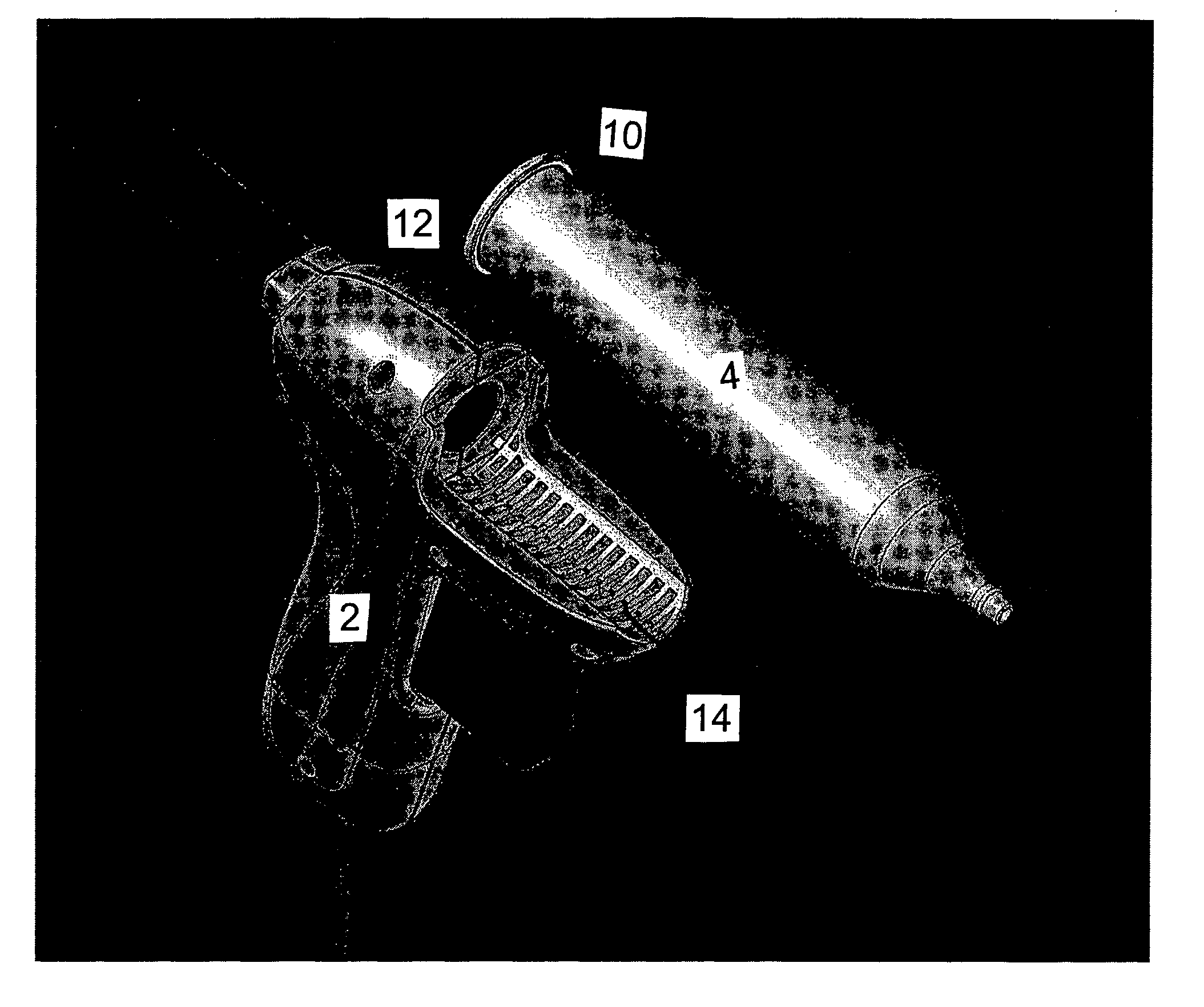
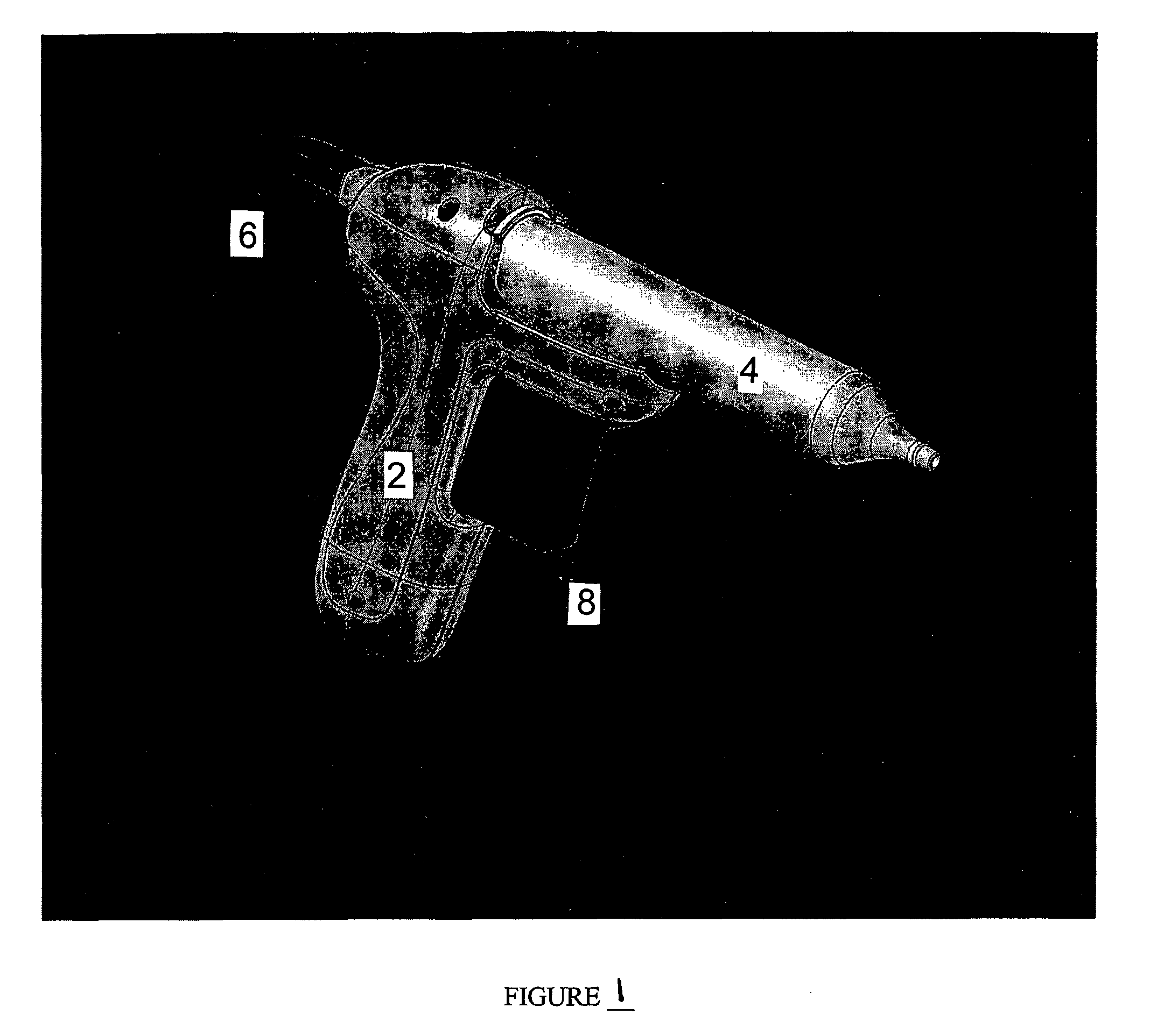
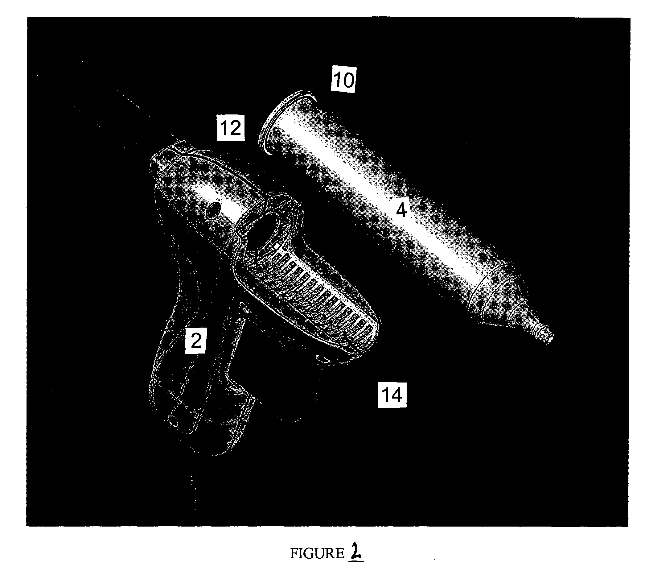
[0017] With reference to FIG. 1, the dispenser of the invention comprises a handle portion 2 and a cartridge portion 4. The handle portion is formed by a shell 3, which may be molded plastic, and includes a plunger 6 slidingly mounted in the shell for movement, and which the user controls by trigger 8. With reference to FIG. 2, it will be appreciated that in the preferred embodiment, the cartridge includes a flange, or lip, 10 at one end and that this flange is configured to engage a slot 12 in a first portion of the handle when the cartridge is in an operative position on the handle as shown in FIG. 1. Handle 2 also includes a trigger portion 14 that extends forward of the first portion to support the trigger 8. It will be appreciated that this construction provides easy installation or removal of the cartridge to facilitate use of a variety of adhesive compositions during a single project. In addition, the preferred construction described allows the cartridge to rotate about its l...


PUM


Abstract

A dispenser for a fluid material includes a handle portion and a cartridge having the material to be dispensed. The cartridge is easily mounted to the handle portion or removed, whereby the handle portion may be used with a variety of cartridges, each of which may contain a selected material. The handle portion includes a plunger that is moved linearly by actuation of a trigger mechanism, which is engaged by a user's finger. The trigger mechanism is configured to release pressure applied to the plunger quickly upon release of pressure on the trigger and to allow the plunger to move away from the cartridge to ensure release of pressure in the material to be dispensed to prevent dripping.

Description

TECHNICAL FIELD [0001] This invention relates to the art of dispensers for liquid or semi-liquid materials. In particular, the invention relates to a dispenser for such materials having a handle portion and a replaceable cartridge and, optionally, a heater for heating the material in the cartridge. BACKGROUND [0002] This invention relates to dispensers of materials that are liquid or semi-liquid, and capable of flowing, including but not limited to adhesives, sealants, caulks, greases, and paints. These materials will be referred to herein generally as fluid materials. Dispensers for these materials are known, and one known dispenser is the hot melt glue gun, which typically uses glue that can be formed into sticks rigid enough at room temperature to be urged into a melt chamber by a feed mechanism that grips the stick. Theses glue guns are limited, however, because they cannot utilize adhesives that are not sufficiently rigid at room temperatures. For example, these glue guns are n...

Claims


Application Information

Patent Timeline
Patent Type & Authority Applications(United States)
IPC IPC(8): B67D5/62B67D5/42B67D7/80B05C17/01B67D7/60B67D7/82
CPCB05C17/00523B05C17/0116B05C17/01
Inventor BELANGER, RICHARD A.MELENDY, PETER S.
Owner ADHESIVE TECH
Why Eureka
Try Eureka