Temperature adjusting device for an LED light source

a technology of temperature adjustment device and led light source, which is applied in the direction of lighting and heating apparatus, printing, instruments, etc., can solve the problems of adverse effects on reading performance, deviating characteristics of led light source, and adverse effects on image quality of read imag

Inactive Publication Date: 2007-05-31
NORITZ CORP
View PDF1 Cites 20 Cited by
  • Summary
  • Abstract
  • Description
  • Claims
  • Application Information

AI Technical Summary

Benefits of technology

[0011] In order to solve the above-mentioned problems, a temperature adjusting device for an LED light source in accordance with the present invention is provided with: an LED light source, a temperature sensor for detecting an ambient temperature of the LED light source, a cooling fan for cooling the LED light source, a driving circuit for driving the cooling fan, a control unit that controls a voltage

Problems solved by technology

With respect to a light source used in a copying machine, an image-reading apparatus and the like, after turning the light source on, a temperature rise tends to occur due to self heat generation to cause changes in the light source characteristics and the resulting adverse effects in image quality of a read image.
However, the control method for on/off controlling the above-mentioned cooling fan has the following problems.
Since, upon turning the cooling fan on, the LED is quickly cooled, the characteristics of the LED tend to deviate.
LED l

Method used


Image

  • Temperature adjusting device for an LED light source
  • Temperature adjusting device for an LED light source
  • Temperature adjusting device for an LED light source

Examples


Embodiment Construction

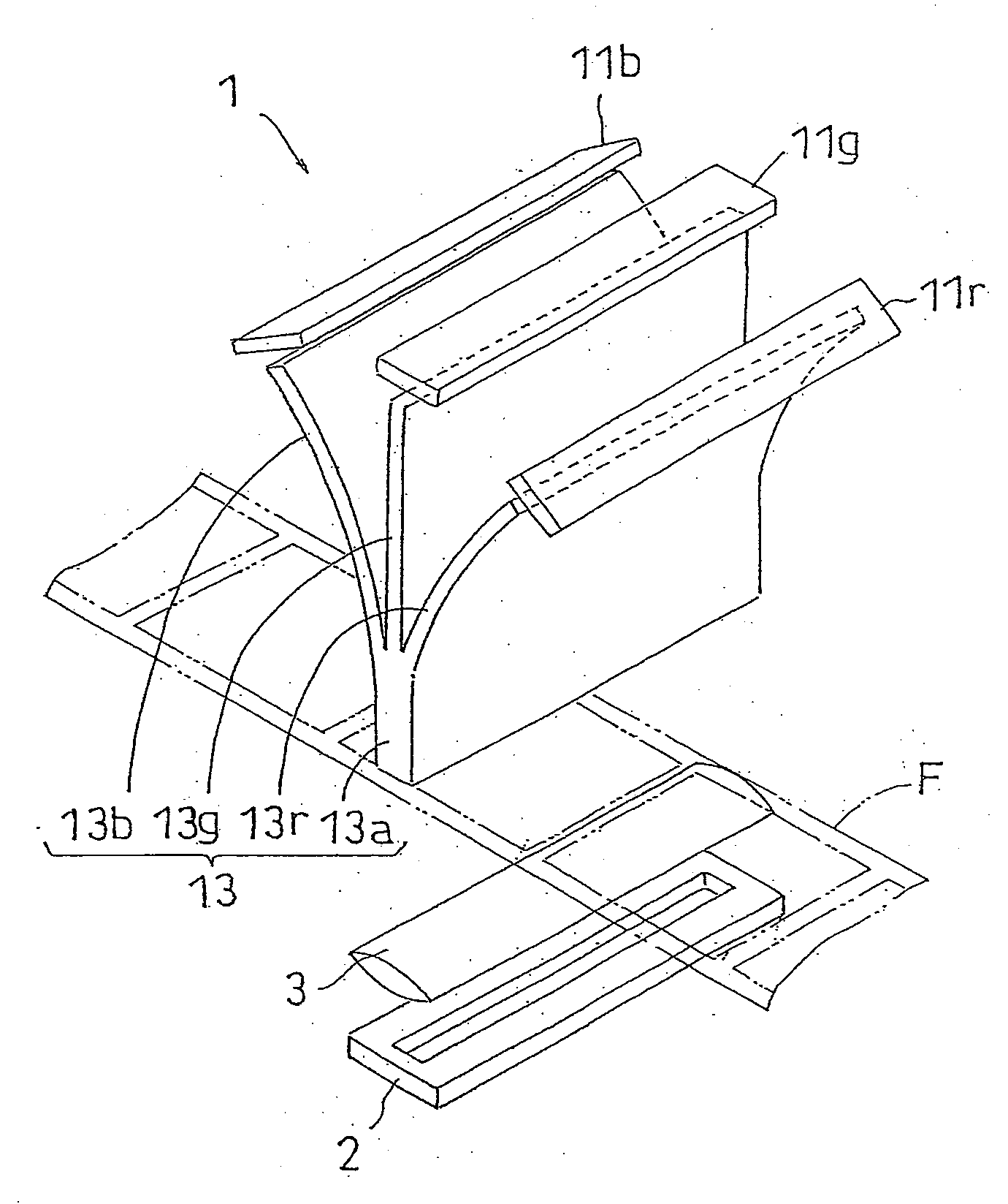
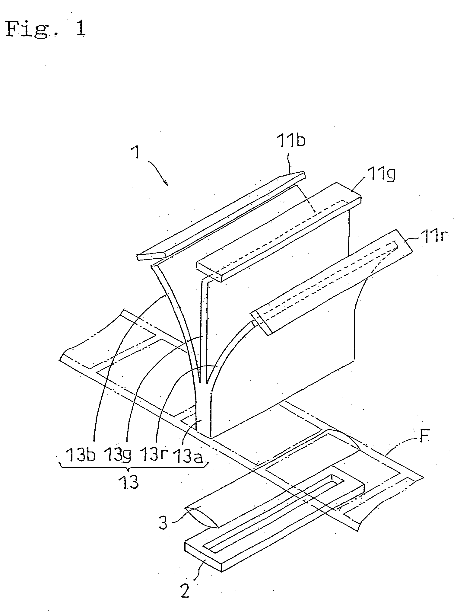
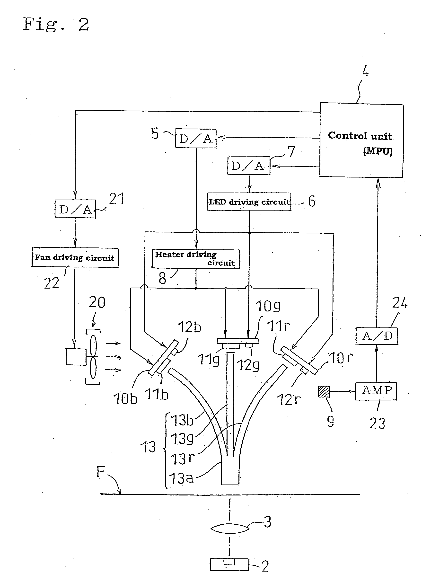
[0027] Referring to Figures, the following description will discuss preferred embodiments of a temperature adjusting device for an LED light source in accordance with the present invention. FIG. 1 is a perspective view that shows a structure of a scanner device in which an LED light source is used. FIG. 2 is a block diagram that explains a temperature adjusting device of the LED light source and functions thereof.

[0028] This scanner device 1 is used for reading frame images formed on a photographic film F, such as a negative-working film and a positive-working film, to form electronic data. With a transporting face on which a photographic film F is transported being sandwiched in between, LED light sources 11r, 11g and 11b serving as reading light sources are placed on one side, and a CCD line sensor 2 serving as a reading sensor is placed on the other side. The red LED light source 11r, the green LED light source 11g and the blue LED light source 11b are installed in order to acqu...


PUM


Abstract

A temperature adjusting device of the present invention is provided with: an LED light source 11r, 11g and 11b, a temperature sensor 9 for detecting an ambient temperature of the LED light source 11r, 11g and 11b, a cooling fan for cooling the LED light source 11r, 11g and 11b, a driving circuit 22 for driving the cooling fan 20, a control unit 4 that controls a voltage to be applied to the cooling fan 20 so as to set the ambient temperature within a predetermined range based upon the results of detection by the temperature sensor 9 and a heater placed near the LED light source 11r, 11g and 11b, and in this arrangement, the control unit is designed to control the applied voltage to the heater so as to reduce the heating value of the heater in cooperation with lighting of the LED light source 11r, 11g and 11b.

Description

CROSS-REFERENCE TO RELATED APPLICATIONS [0001] This is a continuation-in-part of U.S. patent application Ser. No. 10 / 776,158, filed Feb. 11, 2004, which claims priority to Japanese Patent Application No. 2003-35400, filed Feb. 13, 2003, and the disclosure of which is incorporated herein by reference in its entirety.BACKGROUND OF THE INVENTION [0002] 1. Field of the Invention [0003] This invention relates to a temperature adjusting device for an LED light source that is provided with an LED light source, a temperature sensor for detecting an ambient temperature of the LED light source, a cooling fan for cooling the LED light source, a driving circuit for driving the cooling fan, and a control unit which controls a voltage to be applied to the cooling fan so as to set the ambient temperature within a predetermined range based upon the results of detection by the temperature sensor. [0004] 2. Description of the Related Art [0005] With respect to a light source used in a copying machine...

Claims


Application Information

Patent Timeline
IPC IPC(8): F21V23/04G05D23/19G03B27/54
CPCG05D23/1909
Inventor NAKANO, SHOICHI
Owner NORITZ CORP
Why Eureka
Try Eureka