Power controller

a technology of power controller and power supply, which is applied in the direction of dc source parallel operation, transportation and packaging, and cosmonautic vehicles, etc., can solve the problems of increasing the size of the apparatus, and achieve the effects of reducing the heating value of individual switching elements, reducing weight, and reducing siz

Active Publication Date: 2020-09-03
MITSUBISHI ELECTRIC CORP
View PDF0 Cites 1 Cited by
  • Summary
  • Abstract
  • Description
  • Claims
  • Application Information

AI Technical Summary

Benefits of technology

[0013]According to the present invention, the driven states of all the switching elements are determined based on an amount of shunt performed by the entire apparatus for each control cycle, while controlling the switching times of individual switching elements so that the switching times are reduced to a fraction of 1 over the shunt stage count, thereby reducing the heating values of individual switching elements, while eliminating the above problem, that is, the control delay dependent on the shunt stage count. Thus, a highly responsive power controller having a reduced size and reduced weight is provided.

Problems solved by technology

Thus, increased expected maximum heat release from individual switching elements leads to an increased size of the apparatus.

Method used


Image

  • Power controller
  • Power controller
  • Power controller

Examples


embodiment 1

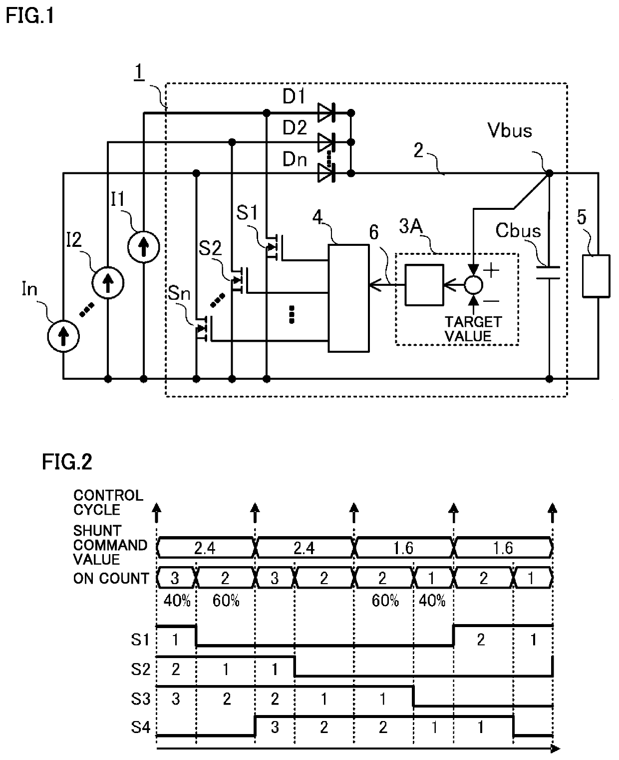
[0024]A power controller according to Embodiment 1 of the present invention is described with reference to the accompanying drawings. FIG. 1 is a circuit diagram of the power controller according to Embodiment 1 of the present invention. As shown in FIG. 1, a power controller 1 is connected to multiple direct-current (DC) power supplies I1 to In (n is an integer greater than or equal to 3) which supply electric power, and a load 5. Power controller 1 controls amounts of electric power that are supplied from DC power supplies I1 to In to load 5.

[0025]DC power supplies I1 to In supply electric power to power controller 1. DC power supplies I1 to In are photovoltaic arrays, for example. Note that the photovoltaic array is an example of a power supply which supplies electric power, and may be replaced with another power supply which supplies power. DC power supplies I1 to In are onboard a satellite in the present embodiment. However, the present invention is not limited thereto, and DC ...

embodiment 2

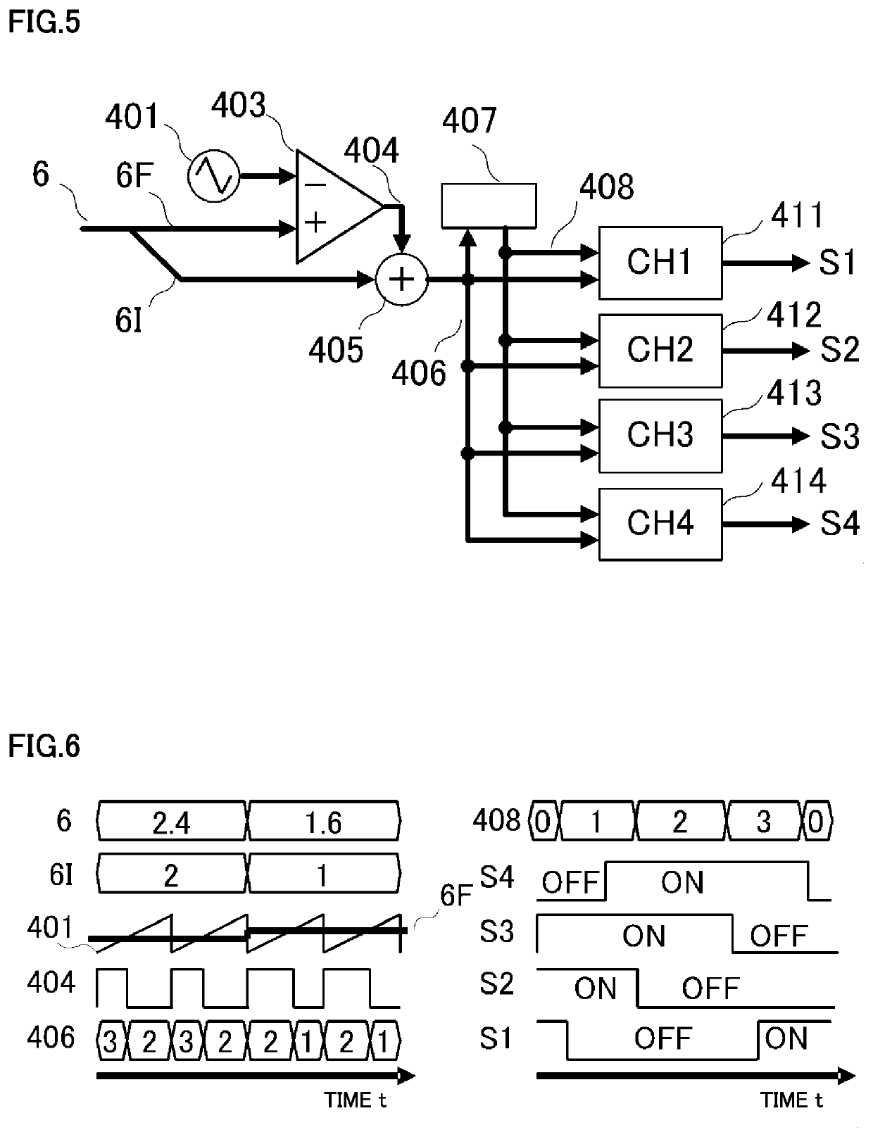
[0053]A power controller according to Embodiment 2 of the present invention is described. Power controller 1 according to the present embodiment is the same as power controller 1 according to Embodiment 1, except for the configuration of a signal generator 4. As with Embodiment 1, power controller 1 according to the present embodiment controls and keeps a bus voltage constant, based on the operation illustrated in the timing chart in FIG. 2. The power controller according. to Embodiment 2 has a configuration same as shown in FIG. 1, and thus the description will not be repeated.

[0054]FIG. 5 is a block diagram showing a configuration of signal generator 4 included in the power controller according to Embodiment 2. FIG. 6 is a diagram showing waveforms generated by each component. In the waveform diagram in FIG. 6, passage of time is indicated on the horizontal axis, and a state of each signal is indicated on the vertical axis. Here, for ease of explanation, a case is illustrated wher...

embodiment 3

[0062]A power controller according to Embodiment 3 of the present invention is described. FIG. 9 is a circuit diagram showing a configuration of the power controller according to Embodiment 3 of the present invention. Unlike the power controller according to Embodiment 1 shown in FIG. 1, power controller 1 in FIG. 9 includes a battery BAT directly connected to a power bus 2. Power controller 1 according to Embodiment 3 is different from power controller 1 according to Embodiment 1 in that power controller 1 according to Embodiment 1 controls and keeps bus voltage Vbus at a constant voltage, whereas power controller 1 according to Embodiment 3 controls and keeps battery BAT charging current Ichg at a constant current.

[0063]The components in FIG. 9 that are given the same reference signs as in FIG. 1 are the same as or corresponding to the components shown in FIG. 1, and description thereof will not be repeated. In power controller 1 shown in FIG. 9, battery BAT is connected to power ...


PUM


Abstract

A power controller includes: a plurality of switching elements provided in one-to-one correspondence with a plurality of power supplies, and each of which switches on or off to switch between supplying and stopping supplying a load with electric power from a corresponding one of the plurality of power supplies; a processing unit which computes an operation amount for adjusting an amount of the electric power supplied to the load; and a signal generator which determines, for each control, a switching-element count indicating a total number of switching elements to be turned on among the plurality of switching elements, and a duty ratio of the switching-element count, based on the operation amount, and generates a drive signal for driving the plurality of switching elements successively, based on the switching-element count and the duty ratio.

Description

TECHNICAL HELD[0001]The present invention relates to a power controller which controls an amount of power supplied to a load.BACKGROUND ART[0002]A power controller is used to control an amount of electric power supplied to a load. For example, a power controller is employed as a bus power supply in a satellite to supply the payload with a voltage stabilized at about 50V or about 100V. A power controller for satellite is known which supplies the load with electric power generated by multiple photovoltaic arrays during sunlight hours, while short-circuiting (hereinafter, referred to as shunting) output of a particular photovoltaic array equivalent to the generated power surplus, thereby controlling the bus voltage to suppress an increase of the power bus voltage.[0003]In such a power controller, the number of stages of photovoltaic arrays depends on a magnitude of electric power demanded to be generated. Conventionally, the photovoltaic arrays include about 10 stages to about 40 stage...

Claims


Application Information

Patent Timeline
Patent Type & Authority Applications(United States)
IPC IPC(8): H02J1/10H02J1/14B64G1/44B64G1/42
CPCH02J1/10H02J1/14B64G1/443B64G1/425B64G1/428H02S40/30Y02E10/50
Inventor OJIKA, SATOSHISAKASHITA, TOMOKAZUOKAMURA, TOSHIOOIKAWA, SHINICHIRO
Owner MITSUBISHI ELECTRIC CORP
Why Eureka
Try Eureka