Combined multi-stream heat exchanger and conditioner/control unit

a multi-stream heat exchanger and control unit technology, applied in lighting and heating apparatus, process and machine control, instruments, etc., can solve the problems of increasing maintenance costs and damage to major engine components, and achieve the effect of reducing the heating value of a natural gas stream

Inactive Publication Date: 2010-08-19
S M E PROD
View PDF17 Cites 0 Cited by
  • Summary
  • Abstract
  • Description
  • Claims
  • Application Information

AI Technical Summary

Benefits of technology

[0015]In one embodiment, a method of reducing a heating value of a natural gas stream comprises flowing the natural gas stream through a first coil of a heat exchanger, cooling the natural gas stream, thereby separating a liquid portion of the natural gas stream having a greater heat value than the rest of the cooled natural gas stream, flowing the liquid portion through a second coil of the heat exchanger, flowing the cooled natural gas stream over the first and second coils, heating the cooled natural gas stream flowing over the first and second coils using the natural gas stream flowing through the first coil, and heating the liquid portion flowing through the second coil using the heated natural gas stream flowing over the first and second coils.

Problems solved by technology

High BTU gas can quickly damage major engine components and dramatically increase maintenance cost.

Method used


Image

  • Combined multi-stream heat exchanger and conditioner/control unit
  • Combined multi-stream heat exchanger and conditioner/control unit
  • Combined multi-stream heat exchanger and conditioner/control unit

Examples


Embodiment Construction

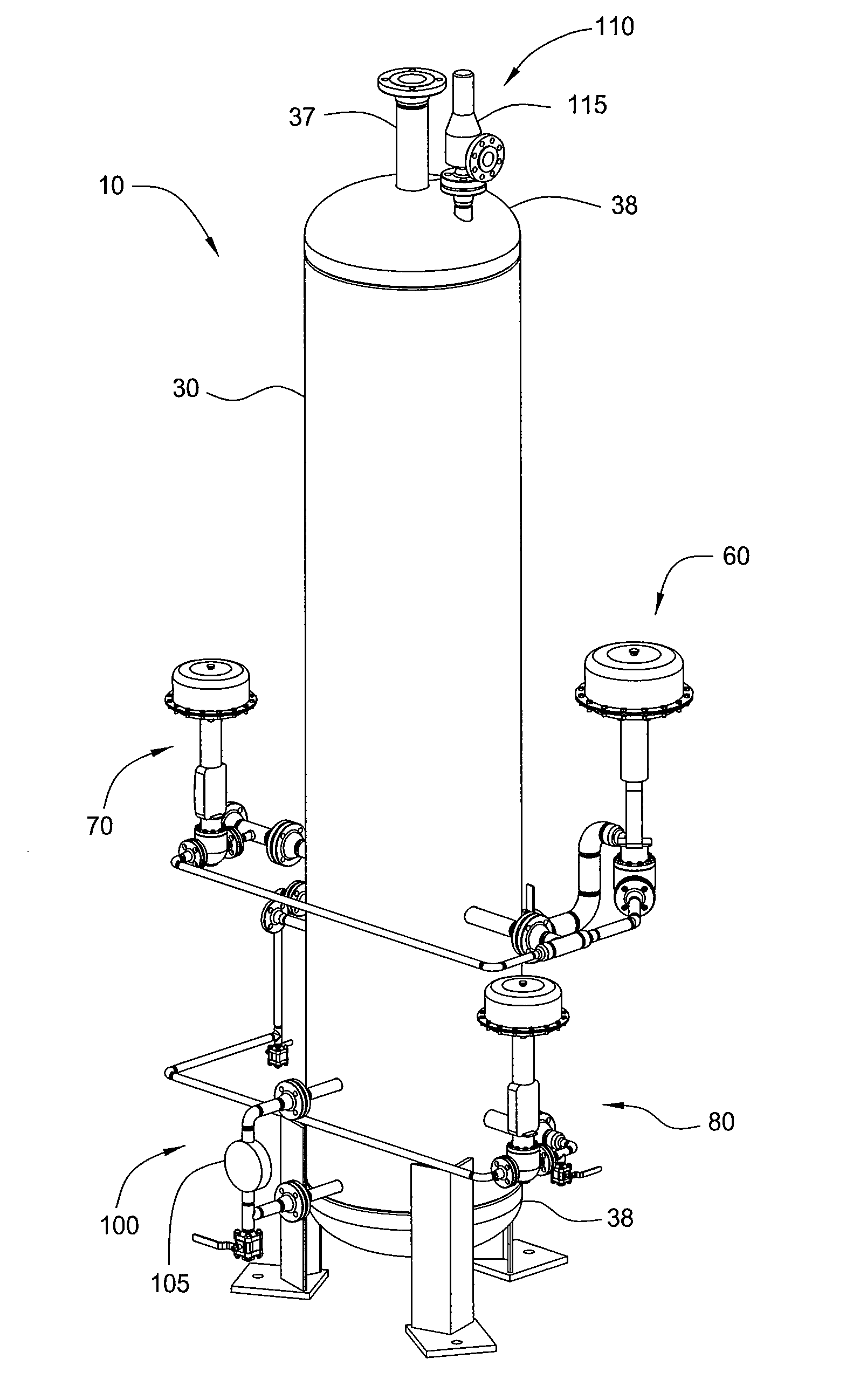
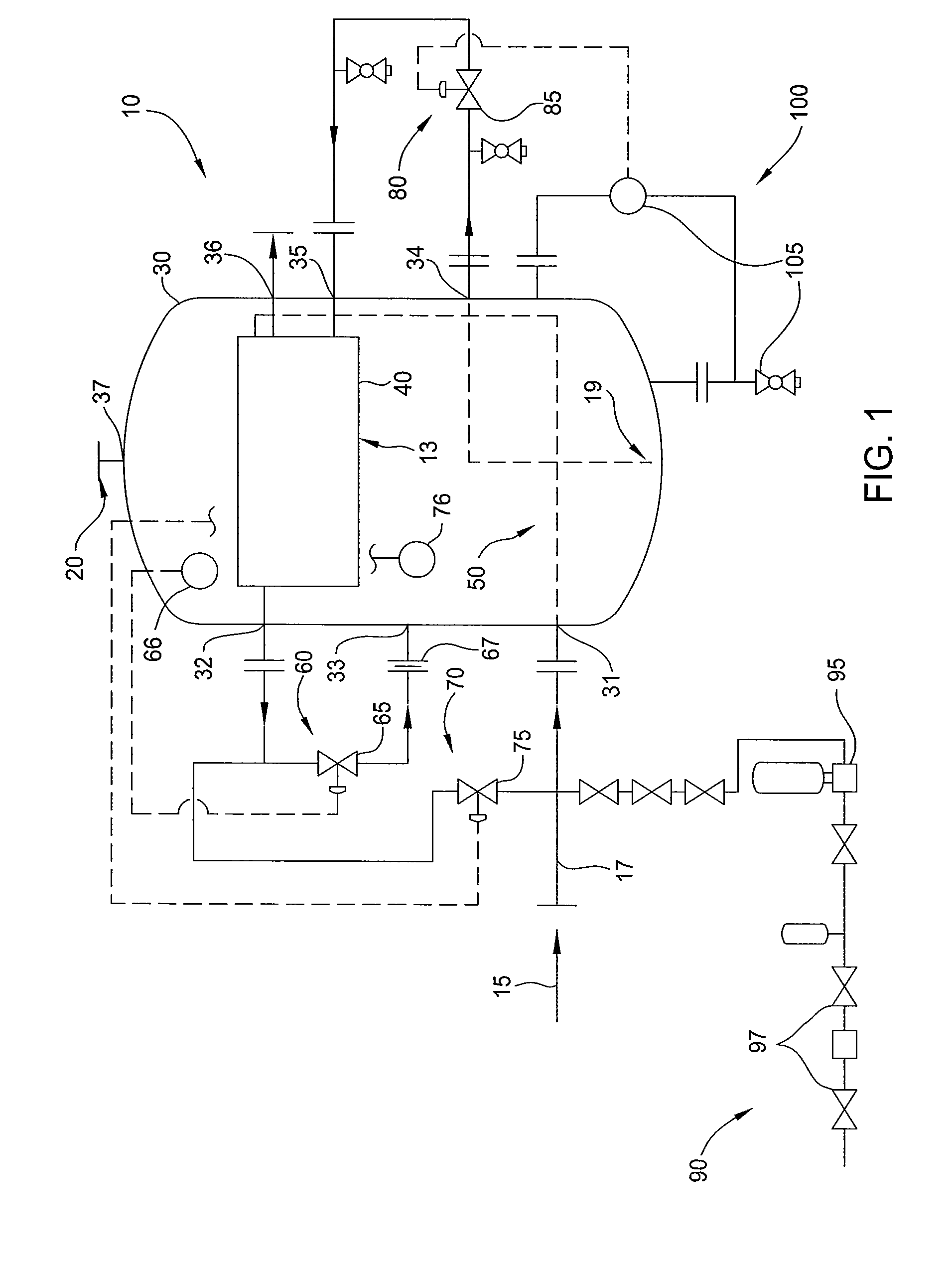
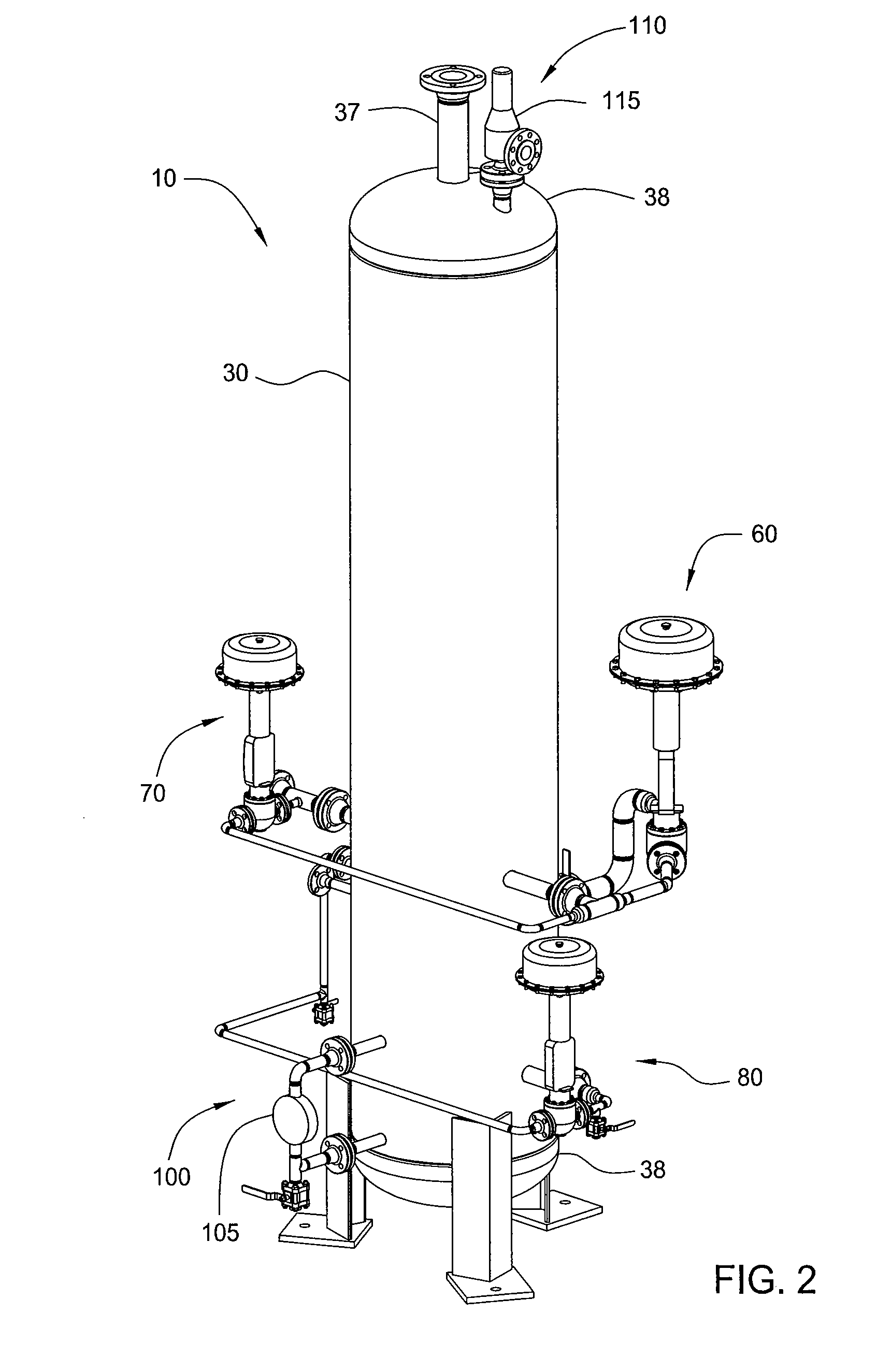
[0049]FIG. 1 illustrates a process and instrumentation diagram of a system 10. The system 10 is operable to treat a variety of fluids, such as hydrocarbon bearing fluids. In one embodiment, the system 10 may be a fuel gas conditioning unit operable to reduce the heating value of a gas stream, by separating and removing propane and heavy hydrocarbons from the gas stream to provide a lean lower BTU fuel stream. In one embodiment, the system 10 may be a dew point control unit operable to control the hydrocarbon dew point of a gas stream by lowering the hydrocarbon dew point of the gas stream to prevent liquid formation in the gas stream or by increasing the hydrocarbon dew point of a separated portion of the gas stream to stabilize the separated portion of the gas stream, for transfer to a pipeline or other end-user consumer of gas.

[0050]In one embodiment, the system 10 is used to treat a natural gas stream 15 to produce a conditioned fuel gas stream 20. The conditioned fuel gas stream...


PUM


Abstract

Methods and apparatus for heating and cooling portions of a fluid are provided. The method may include flowing a stream of a fluid through a heat exchanger, separating a liquid component from the stream of the fluid, flowing the liquid component through the heat exchanger, and redirecting the flow of the stream back through the heat exchanger, thereby cooling the initial stream of fluid flowing through the heat exchanger and heating the liquid component flowing through the heat exchanger. The apparatus may include a housing, a heat exchanger disposed within the housing, a refrigeration system in fluid communication with the heat exchanger, and a control system in fluid communication with the heat exchanger.

Description

CROSS-REFERENCE TO RELATED APPLICATIONS[0001]This application claims benefit of U.S. Provisional Application Ser. No. 61 / 186,361, which was filed on Jun. 11, 2009, and is a continuation-in-part of U.S. patent application Ser. No. 12 / 372,604, which was filed on Feb. 17, 2009, the disclosures of which are hereby incorporated by reference in their entirety.BACKGROUND OF THE INVENTION[0002]1. Field of the Invention[0003]Embodiments of the invention relate to methods and apparatus for treating a fluid, and in particular to heating and cooling portions of the fluid. Embodiments of the invention also relate to a fuel gas conditioning unit. Embodiments of the invention further relate to a dew point control unit. In addition, embodiments of the invention relate to a combination of a multi-stream heat exchanger and a fuel gas conditioning unit or a dew point control unit.[0004]2. Description of the Related Art[0005]Modern lean burn gas fueled engines are sensitive to the gas heating value. Hi...

Claims


Application Information

Patent Timeline
Patent Type & Authority Applications(United States)
IPC IPC(8): F28D15/00
CPCF25J3/0238C10G2300/1025F25J2200/02F25J2200/70F25J2205/04F25J2210/06F25J2220/64F25J2240/02F25J2270/12F25J2270/60F25J2290/40F25J2290/42F25J2290/44F28D7/0066F28D7/08G05D9/00G05D27/00C10G5/06C10L3/10F25J3/0209F25J3/0233F25J5/002F28D7/087F28D7/1615
Inventor JOHNKE, ANDREW FRANCISLEWIS, W. LARRY
Owner S M E PROD
Why Eureka
Try Eureka