Power controller
a technology of power controller and power supply, which is applied in the direction of dc source parallel operation, transportation and packaging, and cosmonautic vehicles, etc., can solve the problems of increasing the size of the apparatus, and achieve the effects of reducing the heating value of individual switching elements, reducing weight, and reducing siz
- Summary
- Abstract
- Description
- Claims
- Application Information
AI Technical Summary
Benefits of technology
Problems solved by technology
Method used
Image
Examples
embodiment 1
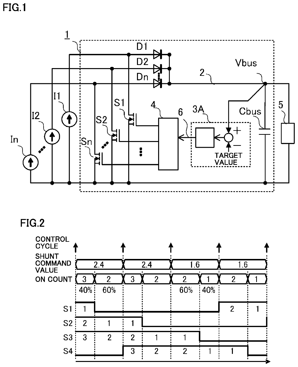
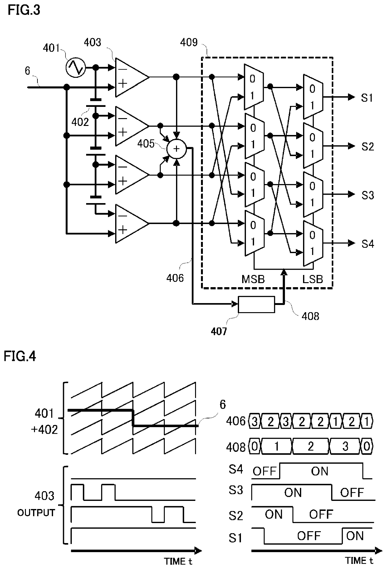
[0024]A power controller according to Embodiment 1 of the present invention is described with reference to the accompanying drawings. FIG. 1 is a circuit diagram of the power controller according to Embodiment 1 of the present invention. As shown in FIG. 1, a power controller 1 is connected to multiple direct-current (DC) power supplies I1 to In (n is an integer greater than or equal to 3) which supply electric power, and a load 5. Power controller 1 controls amounts of electric power that are supplied from DC power supplies I1 to In to load 5.
[0025]DC power supplies I1 to In supply electric power to power controller 1. DC power supplies I1 to In are photovoltaic arrays, for example. Note that the photovoltaic array is an example of a power supply which supplies electric power, and may be replaced with another power supply which supplies power. DC power supplies I1 to In are onboard a satellite in the present embodiment. However, the present invention is not limited thereto, and DC ...
embodiment 2
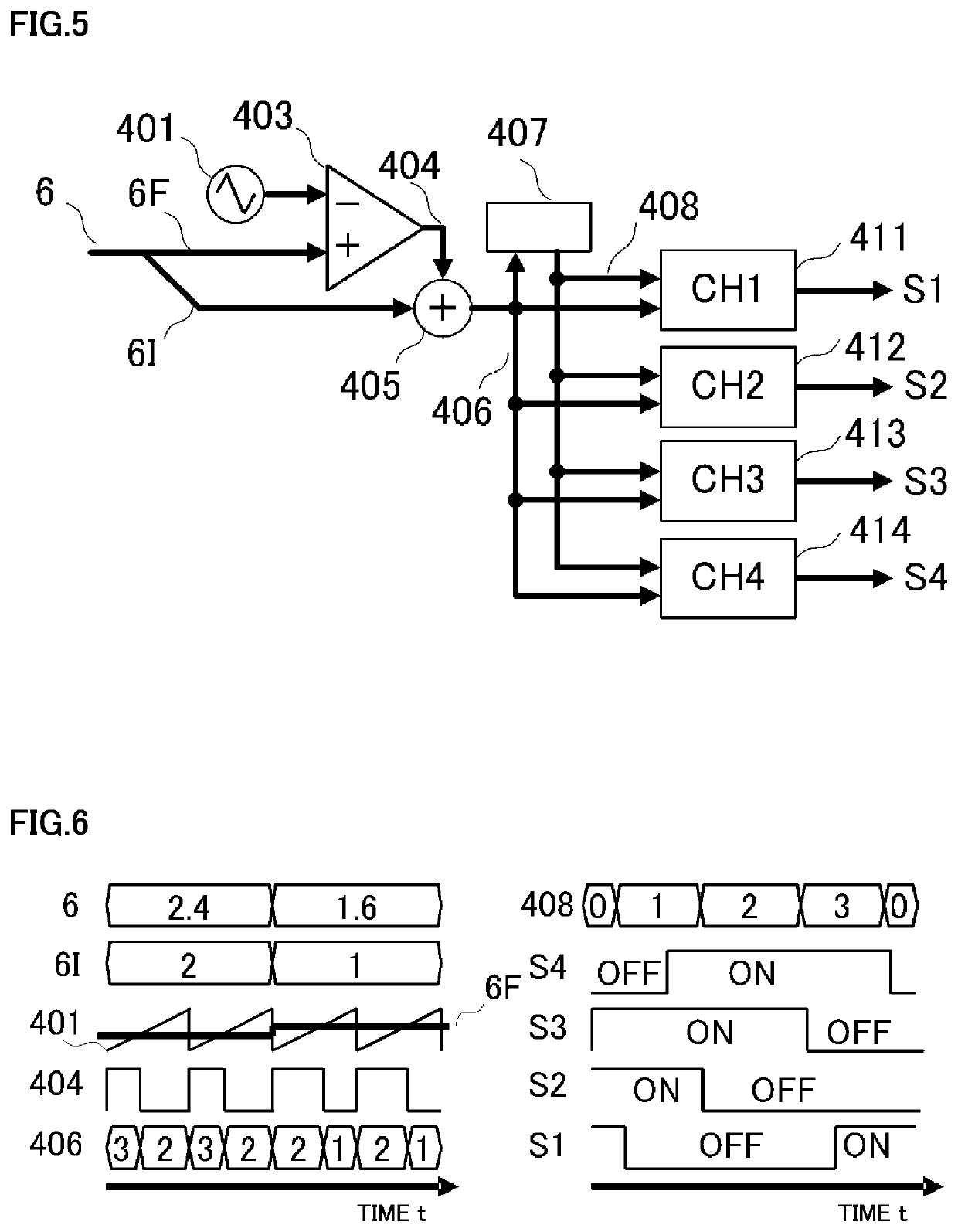
[0055]A power controller according to Embodiment 2 of the present invention is described. Power controller 1 according to the present embodiment is the same as power controller 1 according to Embodiment 1, except for the configuration of a signal generator 4. As with Embodiment 1, power controller 1 according to the present embodiment controls and keeps a bus voltage constant, based on the operation illustrated in the timing chart in FIG. 2. The power controller according to Embodiment 2 has a configuration same as shown in FIG. 1, and thus the description will not be repeated.
[0056]FIG. 5 is a block diagram showing a configuration of signal generator 4 included in the power controller according to Embodiment 2. FIG. 6 is a diagram showing waveforms generated by each component. In the waveform diagram in FIG. 6, passage of time is indicated on the horizontal axis, and a state of each signal is indicated on the vertical axis. Here, for ease of explanation, a case is illustrated where...
embodiment 3
[0064]A power controller according to Embodiment 3 of the present invention is described. FIG. 9 is a circuit diagram showing a configuration of the power controller according to Embodiment 3 of the present invention. Unlike the power controller according to Embodiment 1 shown in FIG. 1, power controller 1 in FIG. 9 includes a battery BAT directly connected to a power bus 2. Power controller 1 according to Embodiment 3 is different from power controller 1 according to Embodiment 1 in that power controller 1 according to Embodiment 1 controls and keeps bus voltage Vbus at a constant voltage, whereas power controller 1 according to Embodiment 3 controls and keeps battery BAT charging current Ichg at a constant current.
[0065]The components in FIG. 9 that are given the same reference signs as in FIG. 1 are the same as or corresponding to the components shown in FIG. 1, and description thereof will not be repeated. In power controller 1 shown in FIG. 9, battery BAT is connected to power ...
PUM
 Abstract
Description
Claims
Application Information
 - R&D
- Intellectual Property
- Life Sciences
- Materials
- Tech Scout
- Unparalleled Data Quality
- Higher Quality Content
- 60% Fewer Hallucinations
Browse by: Latest US Patents, China's latest patents, Technical Efficacy Thesaurus, Application Domain, Technology Topic, Popular Technical Reports.
© 2025 PatSnap. All rights reserved.Legal|Privacy policy|Modern Slavery Act Transparency Statement|Sitemap|About US| Contact US: help@patsnap.com


