Optical disk drive apparatus and optical recording-reproducing apparatus

a technology of optical disk drive and optical recording, which is applied in the direction of data recording, mechanical record carriers, instruments, etc., can solve the problems of disk vibration, difficult to limit airflow in the radius direction of the disk, and the technology has not examined the effect of controlling the vibration of the disk of the cd-rom at a rotational speed of 10000 rpm, and achieves high speed

Inactive Publication Date: 2007-05-31
SONY CORP
View PDF6 Cites 2 Cited by
  • Summary
  • Abstract
  • Description
  • Claims
  • Application Information

AI Technical Summary

Benefits of technology

[0021] As set forth above, according to an embodiment of the present invention, the optical disk drive apparatus and the optical recording-reproducing apparatus are capable of controlling optical disk resonance and allow the optical disk to rotate at high speed with stability when performing high-speed rotation of the optical disk.

Problems solved by technology

However, with the aforementioned methods (Japanese Unexamined Patent Publication No. 2000-357385 and Japanese Patent No. 3630600) where the concentric circle shaped partition wall, the annular protrusion, or the annular groove is provided close to disk surfaces, it appears difficult to limit airflow in the radius direction of the disk for preventing disk vibration when the rotational speed is reaching as high speed as 20000 rpm.
However, the technology has not examined an effect on controlling disk vibration of the CD-ROM at a rotational speed of 10000 rpm or more (i.e., higher than 6000 rpm), specifically, at a rotational speed of approximately 20000 rpm.

Method used


Image

  • Optical disk drive apparatus and optical recording-reproducing apparatus
  • Optical disk drive apparatus and optical recording-reproducing apparatus
  • Optical disk drive apparatus and optical recording-reproducing apparatus

Examples


Embodiment Construction

[0040] Embodiments of the present invention will now be described below with reference to the drawings and it is needless to say that the present invention may not be limited to the embodiments which will follow.

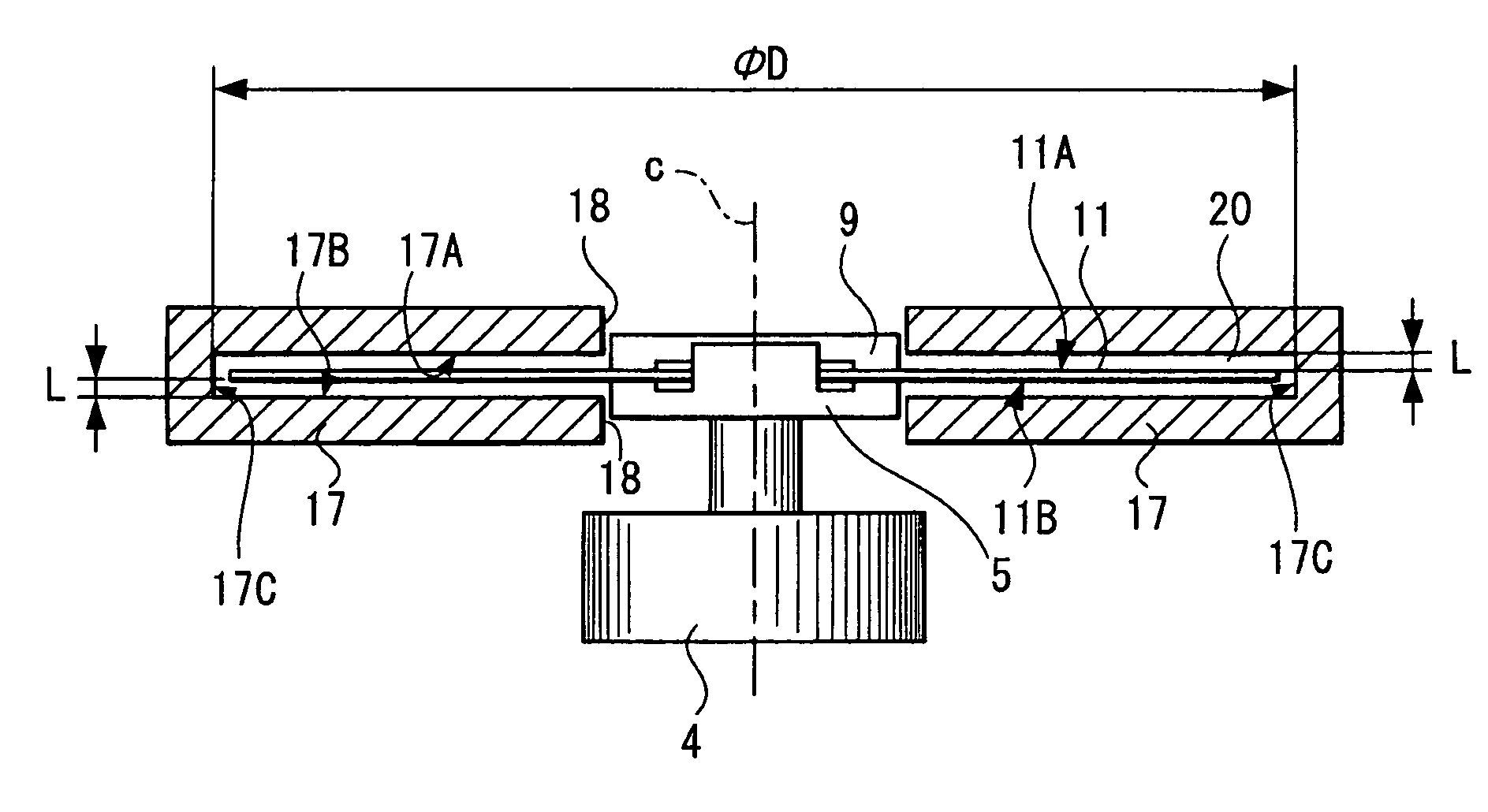
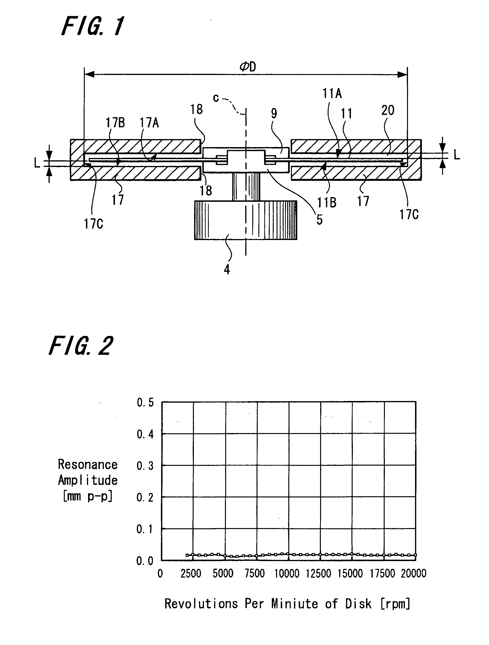
[0041]FIG. 1 is a schematic cross-sectional view showing arrangements of main portions of an optical disk drive apparatus according to an embodiment of the present invention.

[0042] As shown in FIG. 1, an optical disk 11 is loaded on a turntable 5 mounted on a spindle motor 4 and clamped on the turntable 5 with a disk clamper 9. The circumference of the optical disk 11 is enclosed with an enclosure 17 and the optical disk 11 is located at a cylindrical space 20 formed by the enclosure 17. More specifically, the enclosure 17 is used as a space forming unit that forms the cylindrical space 20. The enclosure 17 includes a turntable insertion slot 18 located at the center of the enclosure. It is preferable that a distance L between an upper and lower surfaces 11A and 11B of the...


PUM

PropertyMeasurementUnit
distanceaaaaaaaaaa
diameteraaaaaaaaaa
diameteraaaaaaaaaa

Abstract

An optical disk drive apparatus includes a cylindrical space forming unit that forms a cylindrical space. In the cylindrical space, an optical disk is located such that an upper surface, a lower surface and an edge of an outer circumference of an optical disk face inner surfaces of the cylindrical space forming unit with a predetermined distance.

Description

CROSS REFERENCES TO RELATED APPLICATIONS [0001] The present invention contains subject matter related to Japanese Patent Application JP 2005-346457 filed in the Japanese Patent Office on Nov. 30, 2005, the entire contents of which being incorporated herein by reference. BACKGROUND OF THE INVENTION [0002] 1. Field of the Invention [0003] The present invention relates to an optical disk drive apparatus and an optical disk recording-reproducing apparatus for rotating an optical disk to record data on and / or reproduce data from the optical disk. [0004] 2. Description of the Related Art [0005] In the recent years, attempts have been made on an optical disk drive apparatus to increase recording and reproducing speeds by rotating an optical disk at a rotational speed of approximately 10000 rpm (revolutions per minute). Since air generally has a viscous nature, the air present close to the upper and lower surfaces of the optical disk flows in the radius direction of the optical disk as well...

Claims


Application Information

Patent Timeline
Patent Type & Authority Applications(United States)
IPC IPC(8): G11B3/70
CPCG11B17/043G11B25/04G11B33/08
Inventor TSUKAHARA, NOBUHIKO
Owner SONY CORP
Why Eureka
Try Eureka