Image encoding/image decoding method and image encoding/image decoding apparatus

a technology of image encoding and image decoding, applied in the direction of signal generator with optical-mechanical scanning, color television with bandwidth reduction, signal system, etc., can solve the problems of increased prediction error, prediction does not prove more accurate, prediction precision cannot be expected for an image,

Inactive Publication Date: 2007-05-31
KK TOSHIBA
View PDF3 Cites 189 Cited by
  • Summary
  • Abstract
  • Description
  • Claims
  • Application Information

AI Technical Summary

Problems solved by technology

However, this 4×4-pixel prediction is prediction done only by copying an interpolation value simply in the prediction direction, so that there is a problem that the prediction error increases as the distance with respect to the reference pixel increases.
However, there is a problem that the prediction does not prove right more and more with increase of a distance with respect to the reference pixel like the 4×4-pixel prediction.
There is a problem that prediction precision cannot be expected for an image having a complicated texture since the distance with respect to the reference pixel becomes longer compared with the 4×4-pixel prediction.
However, if the 4×4-pixel prediction is selected at a time when the error signal is not almost generated in the macroblock, minimum 16 bits (maximum 64 bits) must be encoded, resulting in largely deteriorating coding efficiency.
This system is a prediction method premising that an image of an arbitrary encoded block in a frame is similar to that of a block to be predicted, and has a problem that the prediction precision is poor when correlation of blocks in a frame is low.
As discussed above, in the case where interpolated pixels according to a prediction mode is generated from an encoded reference image by a method prescribed in a H.264 high profile, and a predictive image signal is generated by copying the interpolated pixels in a direction prescribed by a prediction mode, there occurs a problem that a prediction error increases as the distance between the prediction pixel and the reference pixel increases in the prediction direction, resulting in that prediction block shapes cannot be coexisted in the macroblock, and the number of encoded bits of mode information cannot be decreased.

Method used


Image

  • Image encoding/image decoding method and image encoding/image decoding apparatus
  • Image encoding/image decoding method and image encoding/image decoding apparatus
  • Image encoding/image decoding method and image encoding/image decoding apparatus

Examples


first embodiment

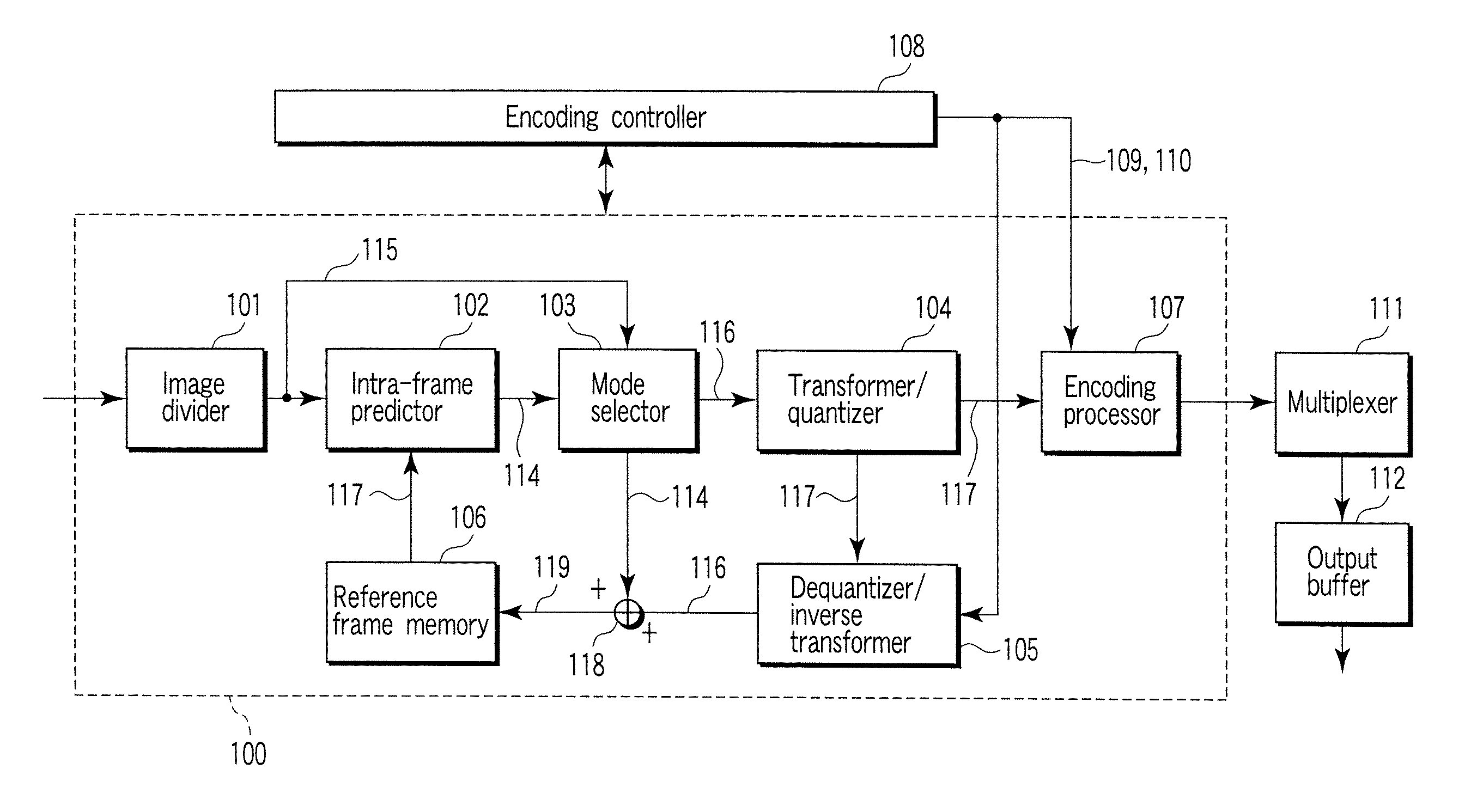
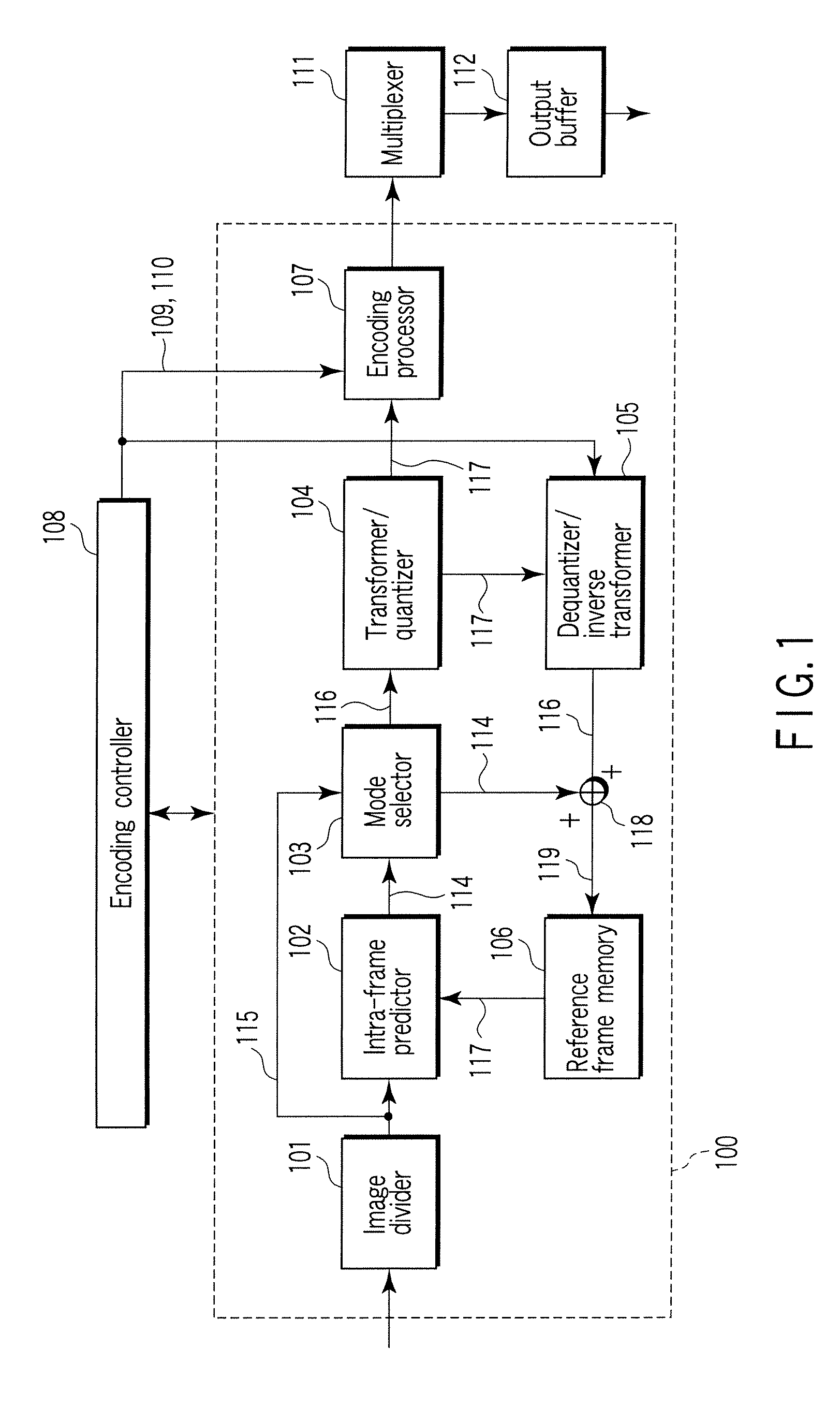
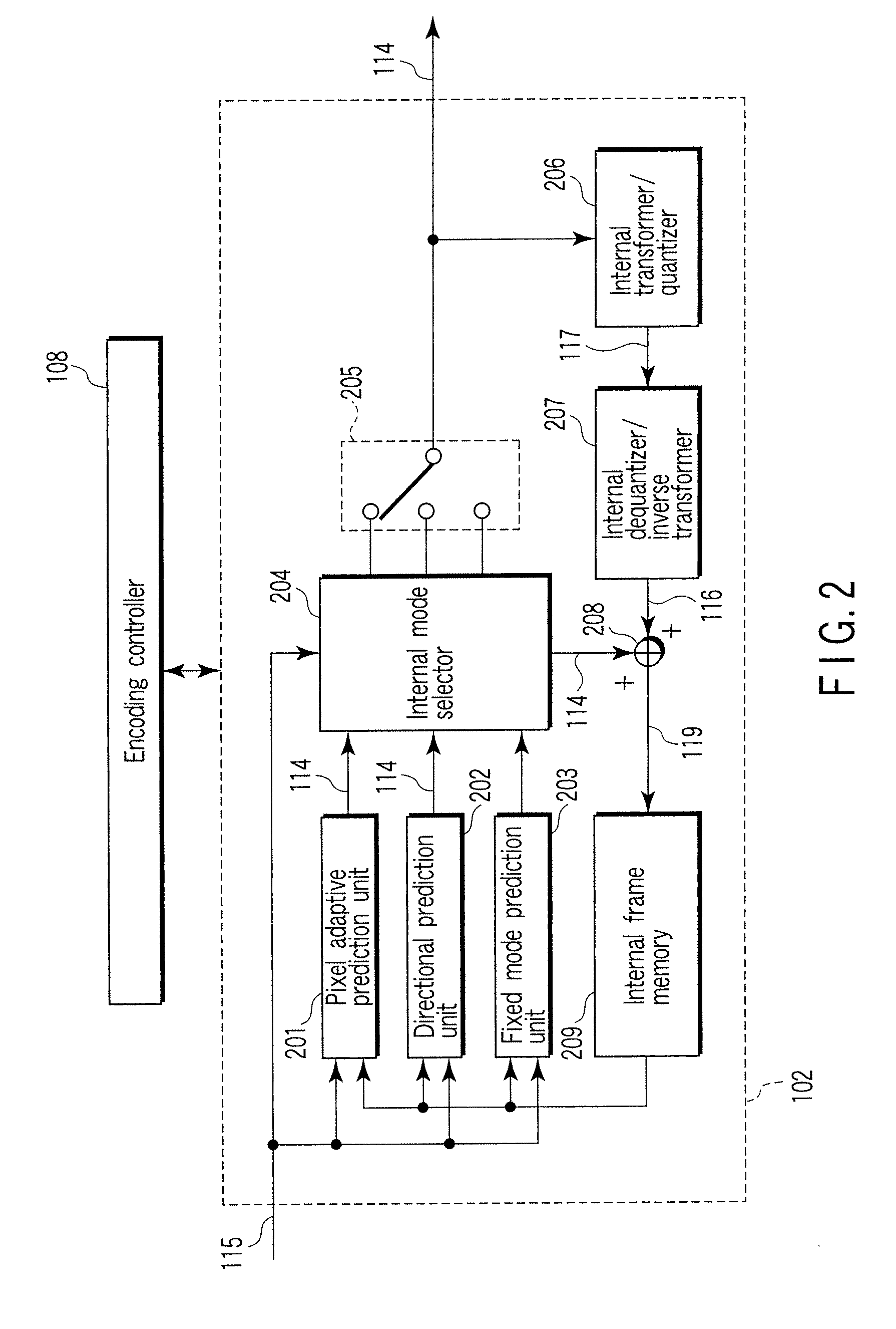
[0046] The video encoding apparatus 100 shown in FIG. 1 is configured to divide a video signal into a plurality of pixel blocks, and encode them. This video encoding apparatus 100 prepares a plurality of frame prediction modes which differ in block size and generation method of a predictive image signal from one another. Intra prediction is a prediction system which prediction is closed in a frame, and predicts a to-be-predicted block using an already encoded reference pixel. It is assumed that an encoding process is executed from an upper left to a lower right as shown in FIG. 4A in this embodiment.

[0047] The video signal input to the video encoding apparatus 100 is divided into a plurality of pixel blocks as an input image signal 115 with an image divider 101. A part of divided input image signal 115 is input to an intra predictor 102, and finally encoded with an encoding processor 107 via a mode selection unit 103 and a transformer / quantizer 107 to output coded data 113.

[0048] ...

second embodiment (

Encoding)

[0146] In a video encoding apparatus 1000 according to the second embodiment shown in FIG. 10, a temporary encoding / number-of-encoded bits counter 1001, an encoding distortion measuring unit 1002, an encoding change-over switch 1003 are added to the video encoding apparatus of the first embodiment. Since the intra predictor and the mode selector differ in function from the first embodiment, reference numerals different from those of the first embodiment are assigned to them.

[0147] In the present embodiment, like reference numerals are used to designate like structural elements corresponding to those like in FIG. 1 and any further explanation is omitted for brevity's sake.

[0148] The video signal input to the video encoding apparatus 1000 is divided into a plurality of pixel blocks with the frame divider 101. Each block is input to the intra predictor 1004 as an input image signal 115. The intra predictor 1004 generates a predictive image signal 114 with all prediction mode...

third embodiment (

Encoding)

[0177] In the third embodiment shown in FIG. 22, a first intra predictor 2202 and a second intra predictor 2203 are added to the second embodiment. Since the frame divider 2201 differ in function from the second embodiment, reference numerals different from those of the second embodiment are assigned to them. In the embodiment of FIG. 10, like reference numerals are used to designate like structural elements corresponding to those like in the embodiment of FIG. 1 and any further explanation is omitted for brevity's sake.

[0178] In the video encoding apparatus 2200 shown in FIG. 22, the first intra predictor 2202 differs from the first intra predictor 2203 only in a prediction block size, and the prediction method is same as the intra predictor 1004 shown in FIG. 11. An image divider 2201 divides an input video signal into a plurality of pixel blocks. At this time, the macroblock is divided in different block shapes. One macroblock is divided into 16 4×4-pixel blocks, and th...


PUM


Abstract

An image coding method includes dividing an input picture into a plurality of pixel block signals, performing intra prediction for extrapolating or interpolating a prediction pixel using reference pixels changed in number according to a distance between the prediction pixel and a reference pixel in plural prediction modes each representing a prediction direction, generating a predictive image signal by extrapolating or interpolating the prediction pixel, calculating a prediction error signal from the pixel block signal and the predictive image signal, selecting one prediction mode of the plural prediction modes using the prediction error signal, and performing entropy-coding using the prediction error signal based on the selected prediction mode.

Description

CROSS-REFERENCE TO RELATED APPLICATIONS [0001] This application is based upon and claims the benefit of priority from prior Japanese Patent Application No. 2005-347121, filed Nov. 30, 2005, the entire contents of which are incorporated herein by reference. BACKGROUND OF THE INVENTION [0002] 1. Field of the Invention [0003] The present invention relates to an image encoding method and an image decoding method for use in moving image or still image, and an image encoding apparatus and an image decoding apparatus. [0004] 2. Description of the Related Art [0005] In recent years, a video encoding method by which coding efficiency is largely improved compared with a conventional art is urged as ITU-TRec.H.264 and ISO / IEC14496-10 (referred to as “H.264”) jointly with ITU-T and ISO / IEC. The conventional encoding system such as ISO / IECMPEG-1,2,4, ITU-TH.261, H.263 performs intra prediction on an orthogonal-transformed frequency domain (DCT coefficients) to reduce the number of encoded bits o...

Claims


Application Information

Patent Timeline
Patent Type & Authority Applications(United States)
IPC IPC(8): H04N11/04H04B1/66H04N19/50H04N19/103H04N19/11H04N19/117H04N19/119H04N19/134H04N19/136H04N19/137H04N19/196H04N19/46H04N19/463H04N19/59H04N19/593H04N19/60H04N19/70H04N19/91
CPCH04N19/176H04N19/147H04N19/61H04N19/11H04N19/182H04N19/124H04N19/14H04N19/152H04N19/117H04N19/103H04N19/51
Inventor TANIZAWA, AKIYUKICHUJOH, TAKESHI
Owner KK TOSHIBA
Why Eureka
Try Eureka