

Camera shake compensation unit, image taking apparatus, image taking system, and method of compensating for image formation position
- Summary
- Abstract
- Description
- Claims
- Application Information
AI Technical Summary
Benefits of technology
Problems solved by technology
Method used
Image

Examples
fourth embodiment
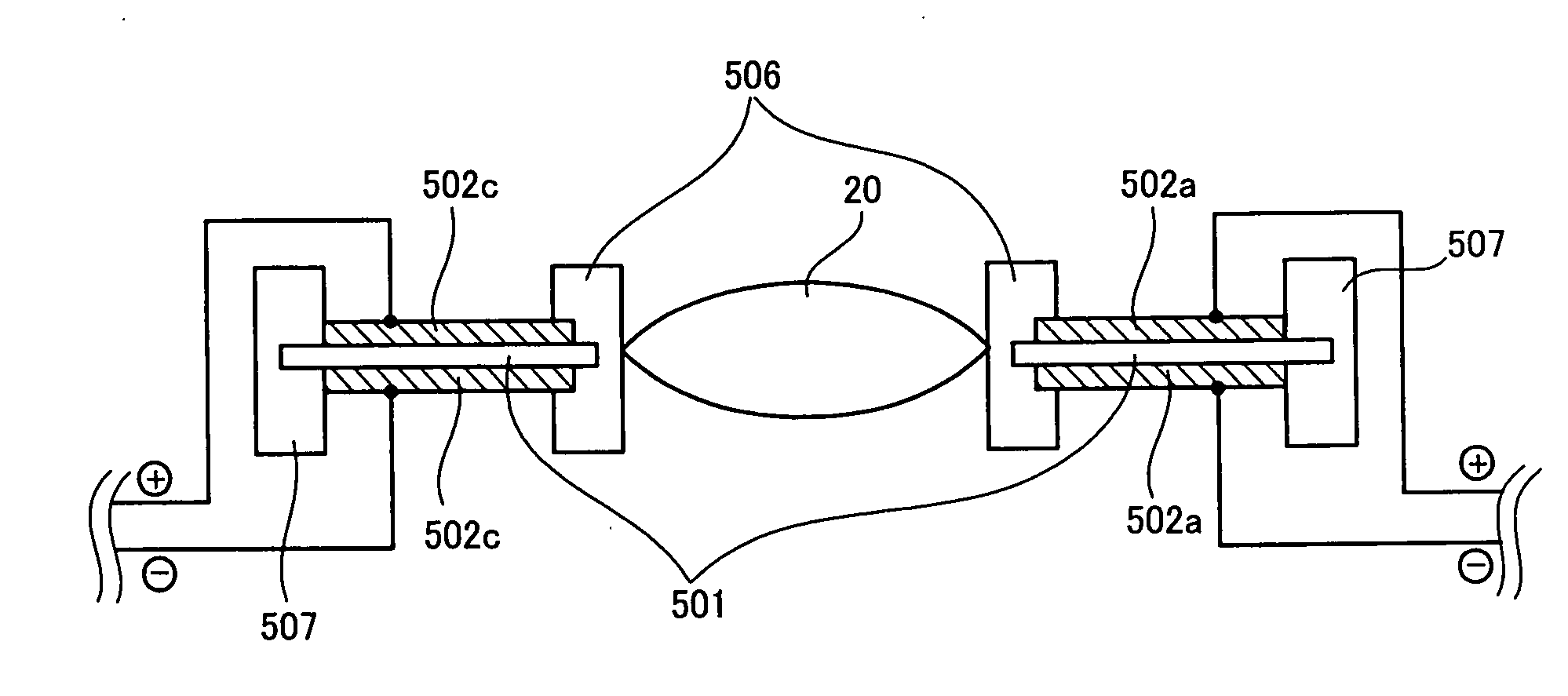
[0235] In the first to third embodiments described above, the external frame 507 to fix the polymer actuator has a square cross section with respect to the plane which is perpendicular to the direction along light incident from a subject. However, the present invention is not limited to this shape and the embodiments described above may employ an external frame whose cross section is circular. Description of such an embodiment will be made below as the fourth embodiment.
[0236]FIG. 10 shows the polymer actuator and the compensation lens which are fixed by an external frame whose cross section is circular.
[0237] Four pairs of electrodes in which one pair consists of an anode and a cathode are mounted in the fourth embodiment in the same way as the case shown in FIG. 3 in which the external frame whose cross section is square is used. Also, applications of voltages to the dielectric elastomer 501 between these pairs of electrodes is carried out in the same way as the case shown in FI...
fifth embodiment
[0238] In the first to fourth embodiments described above, the voltages to be supplied to the four pairs of electrodes to drive the polymer actuator is adjusted by adjustment of the values of the voltages. However, the present invention is not limited to this adjustment method and the embodiments described above may employ another adjustment method, for example, a so-called PWM control method in which adjustment of time intervals when a voltage is applied is carried out in order to control drive of a mobile optical device for compensation for a camera shake, although voltage application has only two stages of On and Off. Description of such an embodiment will be made below as the fifth embodiment.
[0239]FIG. 11 shows a mechanism to apply voltages of two stages of On and Off to the four pairs of electrodes.
[0240] As shown in FIG. 11, there are mounted four switches 503a′, 503b′, 503c′, 503d′ instead of four voltage adjustment sections 503a, 503b, 503c, 503d in FIG. 4. These four swi...
sixth embodiment
[0245] In the first to fifth embodiments described above, compensation for a camera shake is carried out by changing the direction of light incident from a subject by moving the compensation lens on the plane which is perpendicular to the direction along light incident from a subject. However, the present invention is not limited to a lens for compensation for a camera shake and the embodiments described above may employ another type of optical device which can change the direction of light incident from a subject. Also, in order to compensate for a camera shake, it is also possible to employ another way to change the direction of light incident from a subject which is different from the way to move the optical device on the plane which is perpendicular to the direction along light incident from a subject. For example, besides a lens, it is also possible to employ an optical device such as an optical wedge to change the direction of light incident from a subject into the image takin...
PUM
 Abstract
Description
Claims
Application Information