
Vehicle appliance control system

a technology for controlling systems and vehicles, applied in wireless systems/telephones, powerline communications applications, instruments, etc., can solve problems such as increasing the wiring space or the weight of automobiles, and achieve the effect of reducing the wiring space in the vehicle and the weight of the vehicl

Inactive Publication Date: 2007-05-31
PACIFIC INDUSTRIAL CO LTD
View PDF1 Cites 4 Cited by
  • Summary
  • Abstract
  • Description
  • Claims
  • Application Information

AI Technical Summary

Benefits of technology

[0006] Therefore, an object of the present invention is to provide a vehicle appliance control system which can reduce the wiring space in the vehicle and the weight of the vehicle.
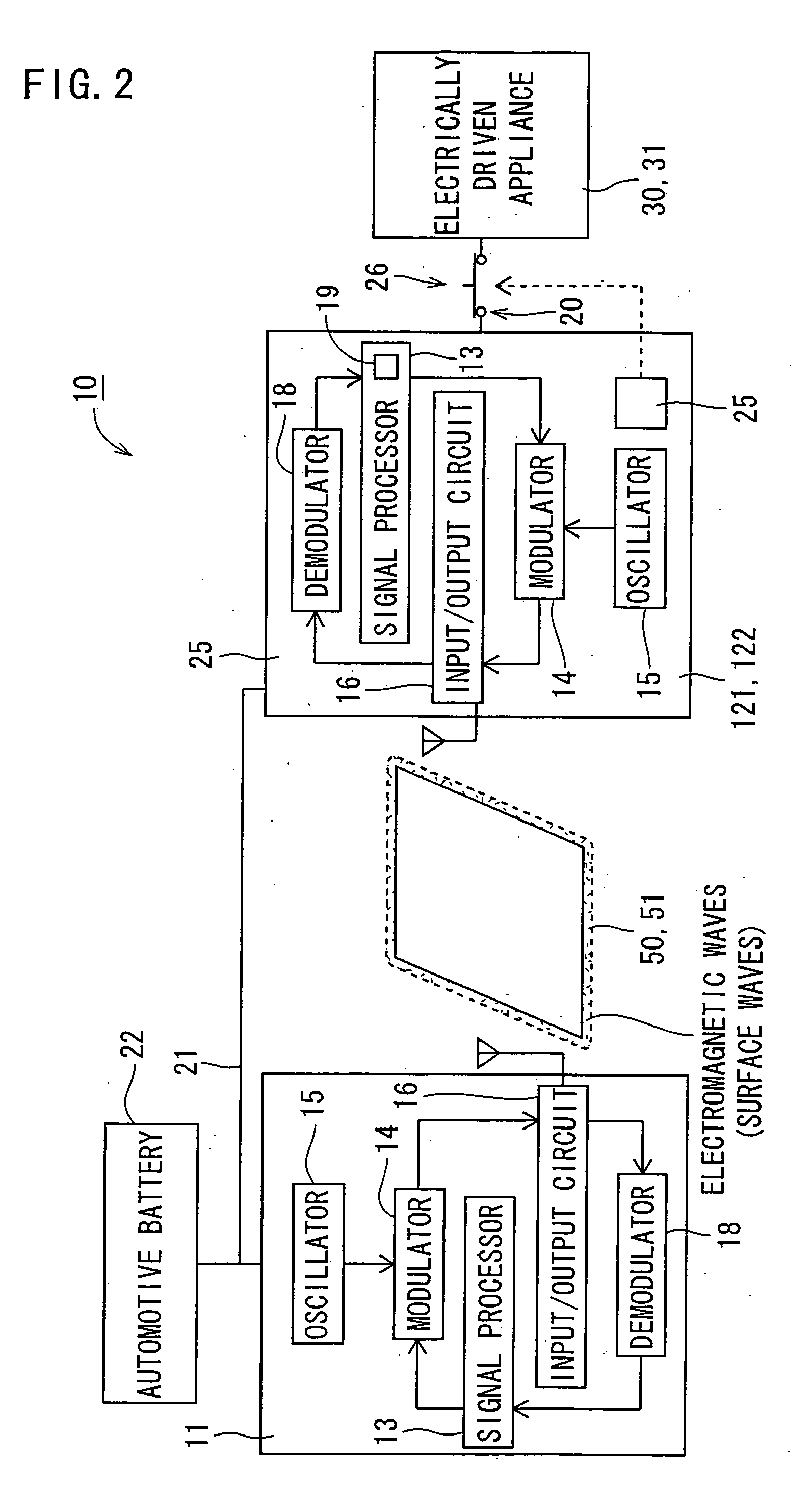
[0008] According to the above-described arrangement, the main communication device superimposes information including an operation command on electromagnetic waves and outputs the electromagnetic waves. Each secondary communication device receives the electromagnetic waves thereby to obtain the information. Thus, since information is transmitted and received by a wireless manner, the wiring space in the vehicle and the weight of the vehicle can be reduced as compared with the conventional arrangement which uses a dedicated communication cable for transmission and reception. Furthermore, since the electromagnetic waves output from the main communication device are surface waves propagating on the surfaces of a plurality of components, power consumption upon output of information can be reduced as compared with the conventional wireless communication by radio waves. Additionally, since the electromagnetic waves output as the surface waves from the main communication device are difficult to be received by a secondary communication device provided on another vehicle, the reliability of communication can be improved.
[0010] According to the above-described system, each secondary communication device superimposes information on electromagnetic waves and outputs the electromagnetic waves. The main communication device receives the electromagnetic waves thereby to obtain the information. Thus, since the information directed to the main communication device is transmitted and received by a wireless manner, the wiring space in the vehicle and the weight of the vehicle can be reduced as compared with the conventional arrangement which uses a dedicated communication cable for transmission and reception. Furthermore, since the electromagnetic waves produced from each secondary communication device are surface waves propagating on the surfaces of a plurality of components, power consumption upon output of information can be reduced as compared with the conventional wireless communication by radio waves. Additionally, since the electromagnetic waves output as the surface waves from each secondary communication device are difficult to be received by a main communication device provided on another vehicle, the reliability of communication can be improved.
[0012] According to the above-described system, the main communication device superimposes information containing an operation command on high-frequency current, outputting the high-frequency current onto a power line. Each secondary communication device obtains the information from the high-frequency current flowing through the power line. Since the power line provided in the vehicle is used as a transmission path for the information containing the operation command, the wiring space in the vehicle and the weight of the vehicle can be reduced as compared with the conventional arrangement which uses a dedicated communication cable for transmission and reception of information. Additionally, since the information output from the main communication device is not received by a secondary communication device provided on another vehicle, the reliability of communication can be improved.
[0014] According to the above-described system, each secondary communication device superimposes information on high-frequency current, outputting the high-frequency current onto a power line. The main communication device obtains the information from the high-frequency current flowing through the power line. Since the power line provided in the vehicle is used as a transmission path for the information directed to the main communication device, the wiring space in the vehicle and the weight of the vehicle can be reduced as compared with the conventional arrangement which uses a dedicated communication cable for transmission and reception of information. Additionally, since the information output from each secondary communication device is not received by a secondary communication device provided on another vehicle, the reliability of communication can be improved.

Problems solved by technology

This causes an increase in the wiring space or in the weight of the automobile.

Method used


Image

  • Vehicle appliance control system
  • Vehicle appliance control system
  • Vehicle appliance control system

Examples


first embodiment

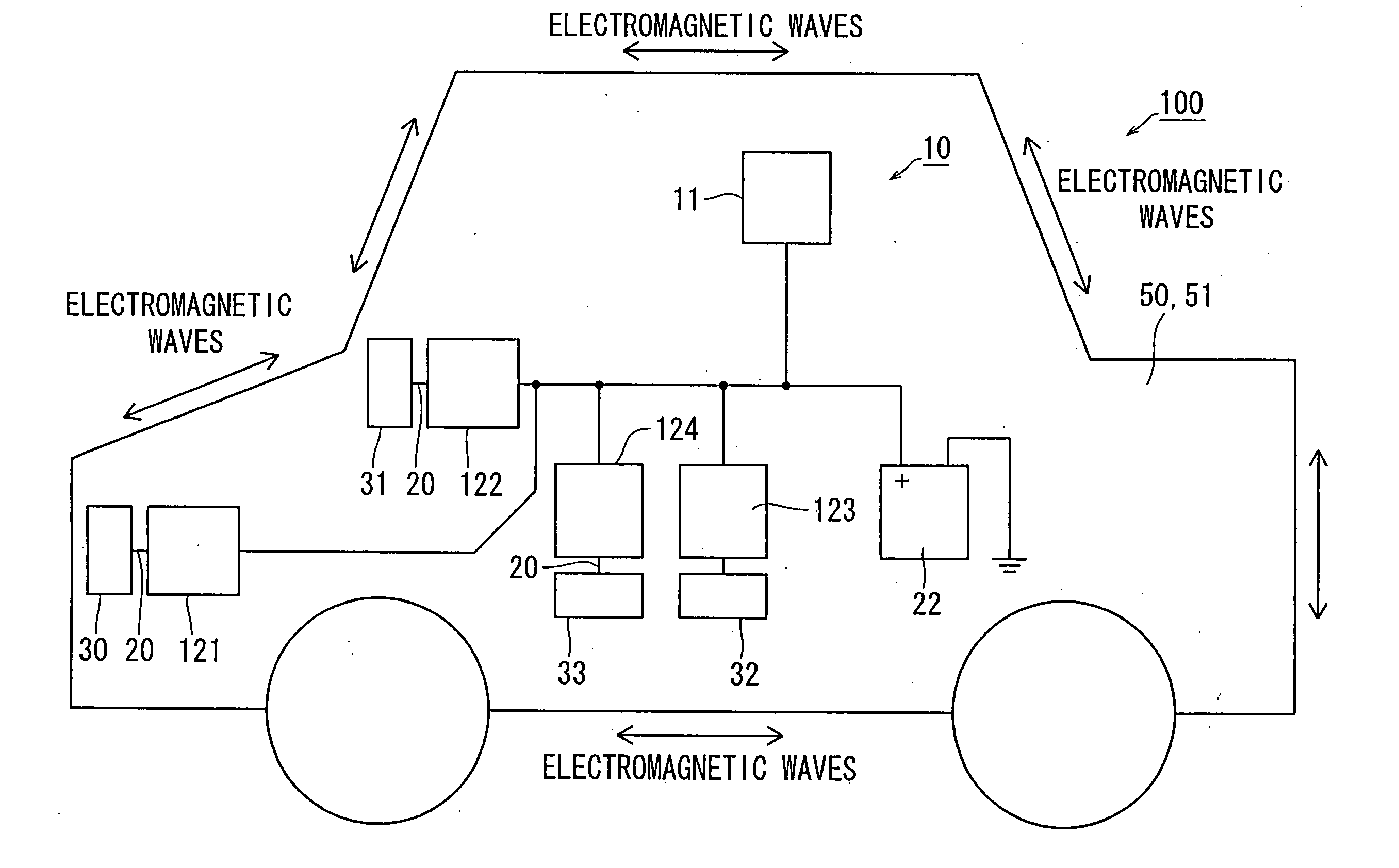
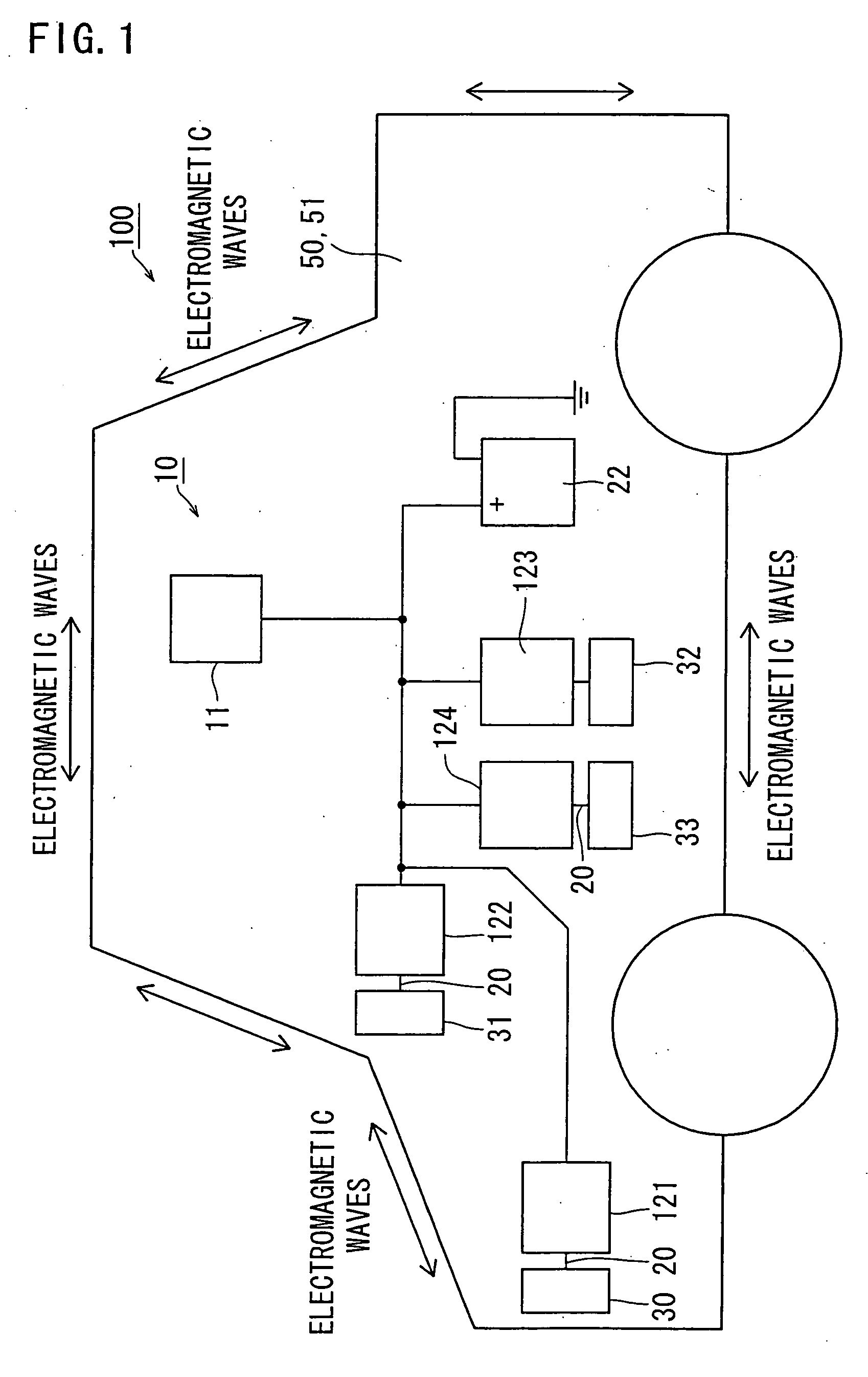
[0024] the present invention will be described with reference to FIGS. 1 to 3. Referring to FIG. 1, reference numeral 10 designates a vehicle appliance control system of the embodiment. The system 10 constitutes an automotive local area network (LAN) provided in an automobile 100 serving as a vehicle in the invention. The system 10 comprises a single main communication device 11 and a plurality of, for example, four, secondary communication devices 121 through 124. These communication devices 11 and 121-124 are dispersed at predetermined positions in the automobile 100.

[0025] The secondary communication devices 121-124 include respective electrical connectors 20 to which various appliances are connected. More specifically, for example, a headlight 30 serving as a lamp in the invention is connected to the electrical connector 20 of the first secondary communication device 121. A wiper motor 31 is connected to the electrical connector 20 of the second secondary communication device 12...

second embodiment

[0042] Referring to FIGS. 4 and 5, the vehicle appliance control system 90 of the second embodiment comprises the main communication device 11, a plurality of secondary communication devices 121-124 and couplers 170-174 provided with the communication devices 11 and 121-124. The couplers 170-174 electrically couples the power cable 21 (serving as a power line in the invention) connected to the positive pole 24 of the automotive battery 22 and supplying electric power to the electrically-driven appliance (the headlight 30, wiper motor 31 or the like) and each of the input / output circuits 16 of main and secondary communication devices 11 and 121-124 therebetween by making use of electromagnetic induction. More specifically, the couplers 170-174 comprise induction coils (not shown) as a major component and supplies, by electromagnetic induction, electric power supplied from the battery 22 through the power cable 21 into the main and secondary communication devices 11 and 121-124, the h...


PUM


Abstract

A vehicle appliance control system includes a main communication device having a main modulator superimposing, on electromagnetic waves, information including an operation command for operating an electrically-driven appliance and outputting the electromagnetic waves as surface waves of components of a vehicle and a plurality of secondary communication devices having respective secondary demodulators obtaining the information from the electromagnetic waves output by the main modulator to have propagated along surfaces of the components. The secondary communication devices are connected to the electrically-driven appliances or the passive appliances, are capable of communicating with the main communication device, and operate the electrically-driven appliances based on the operation command from the main communication device.

Description

BACKGROUND OF THE INVENTION [0001] 1. Field of the Invention [0002] The present invention relates to a vehicle appliance control system provided on a vehicle. [0003] 2. Description of the Related Art [0004] Conventional vehicle appliance control systems-comprise a secondary communication device driving electrically-driven appliances provided in a vehicle and a communication cable serving as a signal transmission path provided between the secondary communication device and a main communication device delivering an operation command to the secondary communication device such as coaxial cable, optical fiber cable or the like. JP-A-2000-69009 discloses one of such conventional vehicle appliance control systems. [0005] The number of electrically-driven appliances provided on an automobile has recently been increasing with progress in the automobile technology. As a result, the number of communication cables connecting the secondary and main communication devices to each other has also be...

Claims


Application Information

Patent Timeline
Patent Type & Authority Applications(United States)
IPC IPC(8): G06F7/00
CPCH04B3/548H04B2203/5425H04B2203/5441H04B2203/547H04B2203/5483H04B2203/5495
Inventor OKUBO, YOUICHIKAWASE, SHINICHITSUJITA, YASUHISA
Owner PACIFIC INDUSTRIAL CO LTD
Learn More