Joining Method and a Device for Operating a Fastening Tool

a technology of fastening tool and jointing method, which is applied in the direction of manufacturing tools, couplings, mechanical devices, etc., can solve the problems of high clamping force, detrimental effect, and prior high clamping force, and achieve low structural expenditure, high clamping force, and high punching force

Inactive Publication Date: 2007-06-07
BOLLHOFF VERBINDUNGSTECHNIK GMBH
View PDF8 Cites 10 Cited by
  • Summary
  • Abstract
  • Description
  • Claims
  • Application Information

AI Technical Summary

Benefits of technology

[0011] The high clamping force exerted after the joining operation is to be selected such that deformations of the workpieces at and around the joining area as caused by the joining operation are reduced and that some compression or compacting effect in the joining area of the workpieces is obtained so as to enhance the quality of the joint and to obtain sufficient final strength of the joint. It is important that, after the joining operation, a high punch force is exerted at the joining area at the same time when the high clamping force is exerted in order to prevent the high clamping force from detrimentally affecting the joint. So the total surfaces at and around the joining area are subjected to high forces after the joining operation whereby the above-mentioned advantages are obtained and furthermore reaction and deflection movements of the C-shaped frame of such fastening tools are reduced. A further advantage of the present invention is that the C-frame may be designed so as to be of reduced weight and strength because substantially no clamping force is exerted during the joining operation so that the C-frame is subjected only to the punch force.
[0012] A preferred device of the present invention includes only one hydraulic cylinder which is divided into a piston rod remote work chamber and a piston rod adjacent work chamber by the main piston for the punch. The clamping piston for operating the clamp is disposed in the piston rod work chamber of the hydraulic cylinder, and the sections of the piston rod adjacent work chamber on axially opposite sides of the clamp piston communicate to each other by fluid flow passage means such that the clamping piston can be pressurized on its axially opposite sides by the pressure prevailing in the piston rod adjacent work chamber.
[0013] This structural design of the device is suited to perform the method of the invention. To this end the device preferably has an operating position wherein the piston rod remote work chamber is pressurized by a pressure sufficient for performing the joining operation, and the piston rod adjacent work chamber is depressurized; furthermore, the device preferably has a post operating position wherein both work chambers are pressurized by high pressure such that, after the joining operation, a high clamping force and a high punch force are exerted at the joining area at the same time.
[0014] Since only one hydraulic cylinder with only two work chambers is required for operating the punch and the clamp, this device of the present invention needs only two fluid pressure ports and only two fluid pressure conduits so that the structural expenditure is minimal. Furthermore, the present invention allows for a compact design of the device because the main piston and the clamping piston are “intercalated”. Therefore, in this device of the present invention increasing the stroke of the device by a certain amount will result in the length of the device being increased by a similar amount whereas, in a drive having two separate hydraulic cylinders, increasing the stroke of the device by a certain amount will result in the length of the device being increased by twice the amount.
[0015] In another embodiment of the present invention there are provided two hydraulic cylinders. Since however two work chambers of the two cylinders are permanently communicated with each other by flow passage means, many advantages of the first mentioned embodiment will be present also in this second embodyment. For example this second embodiment requires only two pressure ports which again provides for reduced structurable expenditure and a simplified hydraulic control system.
[0016] An important advantage of the present invention is that the joining operation is not detrimentally affected by clamping forces. When the invention is used e.g. in a tool for setting self-piercing rivets, the self-piercing rivet is enabled freely to be deformed while penetrating into the workpieces. Deformation of the rivet occurs in a precise manner, and the rivet may be spread more than in a conventional method where high clamping forces are exerted during the riveting operation. Furthermore cracking or fissuring of the rivet is avoided by the present invention.

Problems solved by technology

Even though this method does have its advantages, exerting a high clamping force prior and during the joining operation does have also some drawbacks.
Furthermore, exerting a high clamping force prior to the joining operation may also suffer from some drawbacks in a combined method of using rivets and adhesive to join the workpieces because the high clamping force may detrimentally affect compression and flow of the adhesive from the joining area.

Method used


Image

  • Joining Method and a Device for Operating a Fastening Tool
  • Joining Method and a Device for Operating a Fastening Tool
  • Joining Method and a Device for Operating a Fastening Tool

Examples


Embodiment Construction

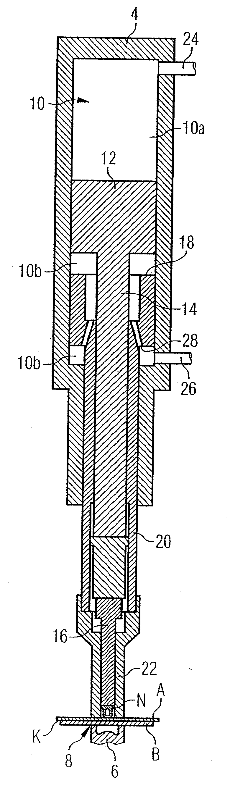
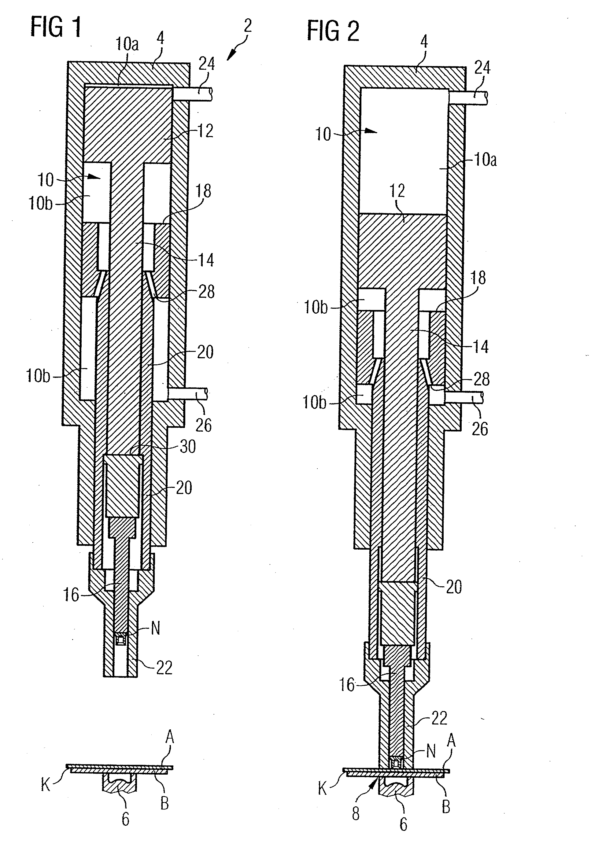
[0027] The fastening tool 2 shown only schematically in the FIGS. 1 to 3 is arranged to make a joint between two (or more) plate-shaped workpieces A and B (metal sheets). In the embodiment as shown the fastening tool 2 is a rivet setting device for setting self-piercing rivets N even though the fastening tool 2 could be another tool such as for example a clinching device. Since self-piercing rivets and self-piercing rivet joints are basically known, they will not be described any further.

[0028] The fastening tool 2 includes a drive comprising a hydraulic cylinder 4, and a die 6, with the workpieces A, B being supported thereagainst. The cylinder 4 is supported on a C-shaped frame (not shown) as is usual in fastening tools of this type.

[0029] The hydraulic cylinder 4 has a cylindrical cavity 10 receiving a main piston 12 with a piston rod 14 so as to be displaceable therein. The piston rod 14 of the main piston 12 is integrally connected to a punch 16 for setting the rivet N.

[0030...


PUM

PropertyMeasurementUnit
clamping forceaaaaaaaaaa
punch forceaaaaaaaaaa

Abstract

In a method for joining at least two plate-shaped workpieces by a fastening tool and a device for operating the fastening tool, the fastening tool comprises a punch for exerting a punch force to perform a joining operation and a clamp for exerting a clamping force upon the workpieces at the joining area. During the joining operation the punch exerts a high punch force to perform the joining operation and the clamp exerts substantially no clamping force to allow for free material deformation in the joining area. After the joining operation both the punch and the clamp exert high forces at the same time to reduce any material deformations of the workpieces and to provide for compression of the workpieces in the joining area. Preferably the invention is used in a riveting tool for setting self-piercing rivets; as an alternative it may be used in a clinching tool.

Description

BACKGROUND OF THE INVENTION [0001] The present invention relates to a method for joining at least two plate-shaped workpieces of similar or different materials by means of a fastening tool, and a device for operating such a fastening tool. Preferably the fastening tool is a riveting tool for setting the self-piercing rivets or a clinching tool for performing a clinching operation. [0002] Various types of drives for fastening tools such as self-piercing riveting and clinching tools have become known. The most common type of drives comprises a hydraulic piston-cylinder-assembly for actuating a punch to perform the joining operation and a further hydraulic piston-cylinder-assembly for actuating a clamp to exert a clamping force upon the workpieces during the joining operation, cf. for example WO93 / 24256 and EP 0675774. In the method and device of EP 0675774 a “substantial” clamping force is exerted prior to and during the joining operation; as said in this publication the clamping forc...

Claims


Application Information

Patent Timeline
Patent Type & Authority Applications(United States)
IPC IPC(8): B23P11/00
CPCB21D39/031Y10T29/5377B21J15/20Y10T29/53709Y10T29/49835Y10T29/49954Y10T29/49943Y10T29/49908Y10T29/49956Y10T29/49837Y10T29/5343Y10T29/49833Y10T403/4966Y10T29/49915B21J15/025
Inventor LANG, HANS JORGDRAHT, TORSTEN
Owner BOLLHOFF VERBINDUNGSTECHNIK GMBH
Why Eureka
Try Eureka