Photoelectric encoder

a technology of photoelectric encoder and encoder, which is applied in the direction of optical conversion of sensor output, instruments, measurement devices, etc., can solve the problems of increasing manufacturing costs, affecting the quality of the signal, and the harmonic of the 3rd order being larger than the harmonic of the 2nd order,

Active Publication Date: 2007-06-07
MITUTOYO CORP
View PDF7 Cites 11 Cited by
  • Summary
  • Abstract
  • Description
  • Claims
  • Application Information

AI Technical Summary

Benefits of technology

[0021] Shifting a plurality of portions of the first grating by the respective different shift amounts makes it possible to remove harmonic components of a plurality of orders.
[0022] Continuously varying the shift amount to deform the grating pattern in the shape o...

Problems solved by technology

Therefore, there is a problem that a harmonic component is superimposed on an output signal at that portion.
However, the methods in which the light receiving array has the phase difference or the line width modulation as described in Patent Documents 4 and 5 need to vary the pattern of the light receiving element, thereby increasing manufacturing costs.
Therefore, it is impossible to remov...

Method used


Image

  • Photoelectric encoder
  • Photoelectric encoder
  • Photoelectric encoder

Examples


Embodiment Construction

[0034] Exemplary embodiments of the present invention will be hereinafter described in detail with reference to the drawings.

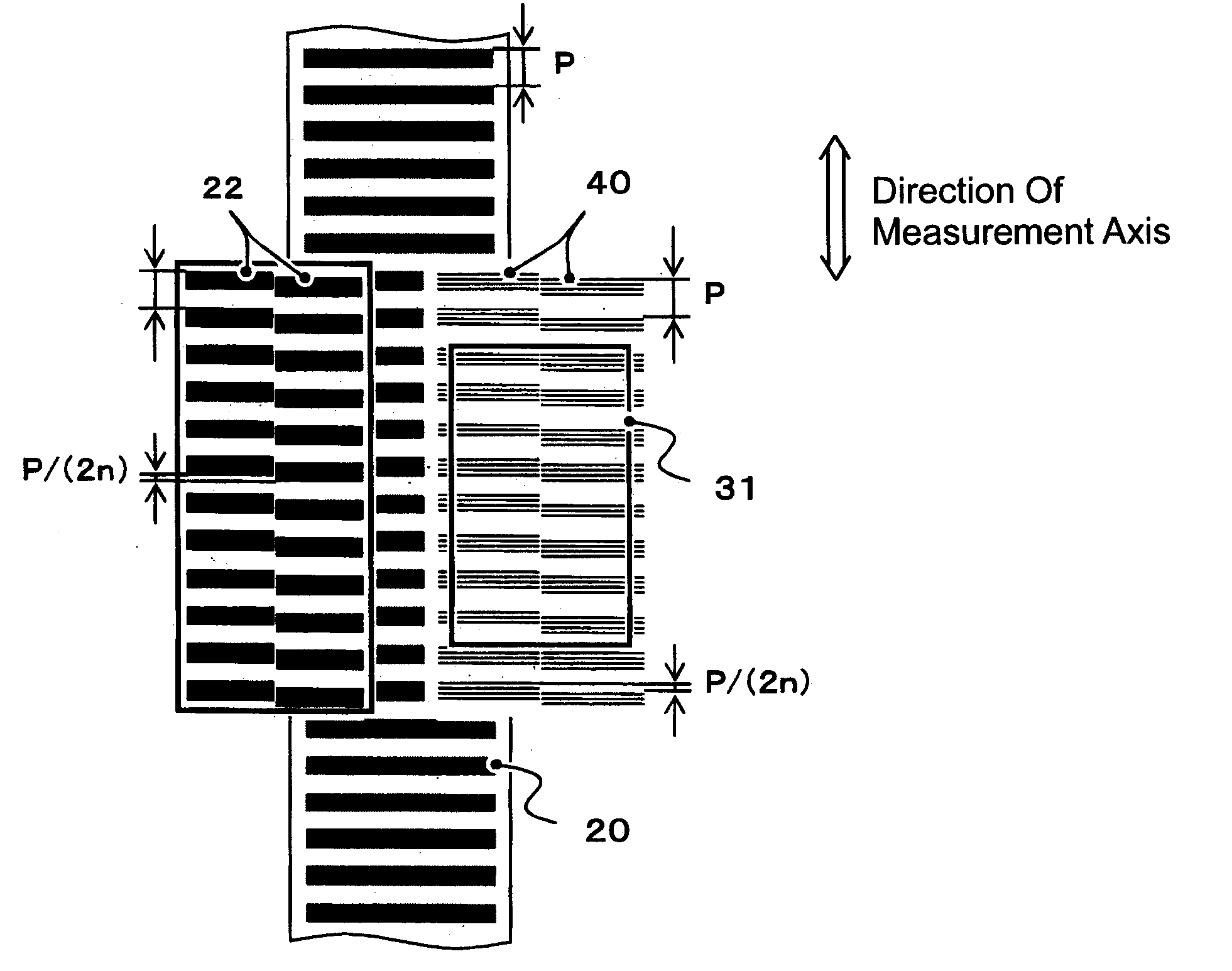
[0035] In a first exemplary embodiment of the present invention applied to the reflection type encoder, as shown in FIG. 4, the pattern of a first grating 22 formed on a glass substrate with low manufacturing costs, on which a light receiving array 31 is to be mounted, is divided in two in a direction perpendicular to a measurement axis. Then, one of the patterns is shifted in the direction of the measurement axis with respect to the other. When n represents the order of a harmonic component to be removed, the corresponding shift amount is represented by a grating pitch P / (2×n). When a harmonic component of the 3rd order is removed, a shift amount is P / 6.

[0036] In the first exemplary embodiment, light emitted from a light source transmits through the first grating 22, reflected by the second grating 20 and generates interference fringes 40 on a light receivi...


PUM


Abstract

A three-grating type photoelectric encoder includes a second grating formed on a scale and first and third gratings disposed on a side of a detector. A part of at least the first grating is shifted in a direction of a measurement axis by P/(2n) (wherein P is a grating pitch, n is the order of a harmonic component to be removed) in order to remove a harmonic component of the nth order. This encoder can be improved with high accuracy by removing harmonic components without increasing manufacturing costs.

Description

CROSS-REFERENCE TO RELATED APPLICATION [0001] The disclosure of Japanese Patent Application No. 2005-352397 filed on Dec. 6, 2005 including specifications, drawings and claims is incorporated herein by reference in its entirety. BACKGROUND OF THE INVENTION [0002] 1. Field of the Invention [0003] The present invention relates to a three-grating type photoelectric encoder which is provided with a second grating formed on a scale and first and third gratings disposed on the side of a detector. In particular, the present invention relates to a photoelectric encoder which can effectively remove harmonic components. [0004] 2. Description of the Related Art [0005] In a so-called three-grating principle used in a linear encoder, as described in, for example, Patent Document 1 (Japanese Patent Laid-Open Publication No. Sho 63-33604, see FIGS. 1 to 3 thereof), three optical gratings serve as a spatial filter. For a transmission type shown in FIG. 1(A), the three optical gratings are a second ...

Claims


Application Information

Patent Timeline
IPC IPC(8): G01D5/36
CPCG01D5/34746
Inventor YAKU, TORUKIRIYAMA, TETSURO
Owner MITUTOYO CORP
Why Eureka
Try Eureka