Eureka AIR delivers breakthrough ideas for toughest innovation challenges, trusted by R&D personnel around the world.

Method for manufacturing composite shoe insole

a composite and shoe insole technology, applied in the field of shoe insole manufacturing, can solve the problems of increasing weakening or breaking the structure uncomfortable sensation for the user, etc., and achieves the effects of reducing the burden on the user, facilitating the use of the shoe insole, and facilitating the use of the sho

Inactive Publication Date: 2007-06-07
YANG KUO NAN
View PDF7 Cites 9 Cited by
  • Summary
  • Abstract
  • Description
  • Claims
  • Application Information

AI Technical Summary

Benefits of technology

[0007] The primary objective of the present invention is to provide a method for manufacturing a composite shoe insole that closely combine the EVA material with the PU material, so that the composite shoe insole has a lighter weight by the EVA material and has a soft elastic feature by the PU material.
[0008] Another objective of the present invention is to provide a method for manufacturing a composite shoe insole, wherein the solid PU material of the shoe insole provides a greater elastic support to a user's foot, thereby providing a comfortable sensation to the user.
[0009] A further objective of the present invention is to provide a method for manufacturing a composite shoe insole, wherein the EVA material of the shoe insole has a lighter weight to reduce the whole weight of the shoe insole, thereby decreasing the burden to the user.
[0010] A further objective of the present invention is to provide a method for manufacturing a composite shoe insole, wherein the proportion, position and size of the EVA material and the PU material can be changed according to the practical requirement so as to provide a comfortable sensation to the user and to reduce the whole weight of the shoe insole, thereby enhancing the versatility of the shoe insole.

Problems solved by technology

However, the PU material has a heavier weight, thereby increasing the burden to the user.
In addition, the PU material easily produces powder when touching the water, thereby weakening or breaking the structure of the shoe insole.
However, the EVA material has a smaller elasticity, thereby easily causing an uncomfortable sensation to the user.

Method used


Image

  • Method for manufacturing composite shoe insole
  • Method for manufacturing composite shoe insole
  • Method for manufacturing composite shoe insole

Examples


Embodiment Construction

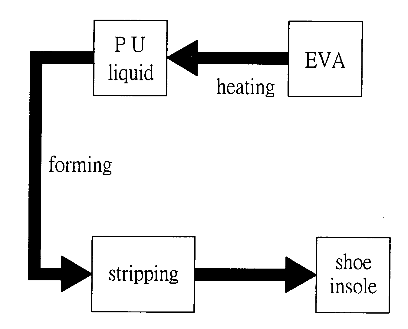
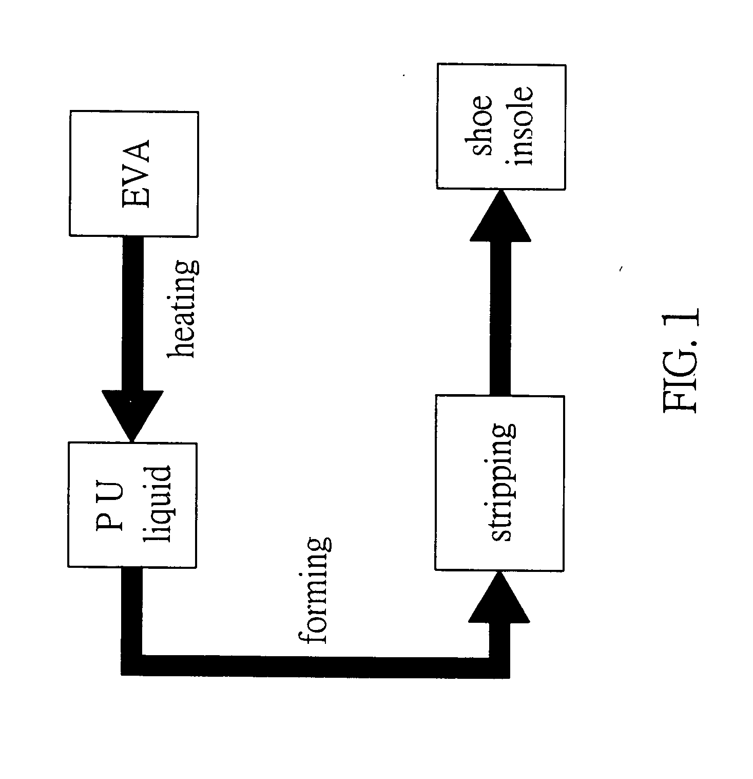
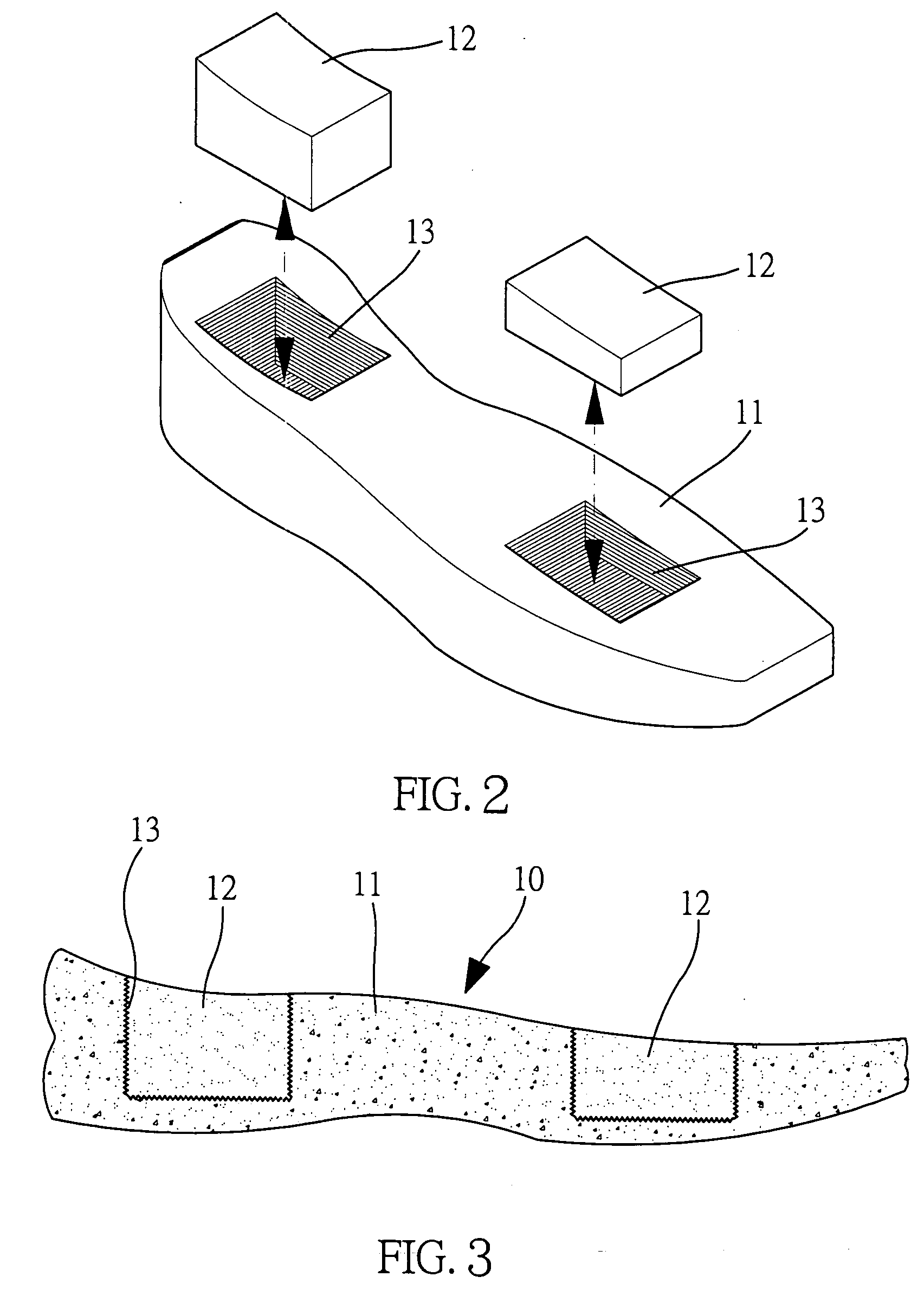
[0022] Referring to the drawings and initially to FIGS. 1-3, a method for manufacturing a composite shoe insole in accordance with the preferred embodiment of the present invention comprises the following steps:

[0023] a) placing EVA (ethyl vinyl acetate) material 11 into a die, wherein the EVA material 11 has at least one bonding zone 13;

[0024] b) applying a PU (polyurethane) film around a peripheral wall of the bonding zone 13 of the EVA material 11;

[0025] c) heating the EVA material 11 to a temperature at about 50° C. to 60° C.;

[0026] d) placing PU material 12 at a liquid state into the bonding zone 13 of the EVA material 11;

[0027] e) solidifying the PU material 12 so that the PU material 12 is combined with the bonding zone 13 of the EVA material 11 to form a shoe insole 10;

[0028] f) stripping the shoe insole 10 from the die to remove the shoe insole 10 which combines the EVA material 11 and the PU material 12.

[0029] In the preferred embodiment of the present invention, th...


PUM

PropertyMeasurementUnit
temperatureaaaaaaaaaa
thicknessaaaaaaaaaa
lengthaaaaaaaaaa

Abstract

A method for manufacturing a composite shoe insole includes a) placing EVA material having at least one bonding zone into a die, b) applying a PU film around a peripheral wall of the bonding zone of the EVA material, c) heating the EVA material, d) placing PU material at a liquid state into the bonding zone, e) solidifying the PU material so that the PU material is combined with the bonding zone to form a shoe insole, and f) stripping the shoe insole from the die to remove the shoe insole. Thus, the composite shoe insole closely combine the EVA material with the PU material, so that the composite shoe insole has a lighter weight by the EVA material and has a soft elastic feature by the PU material.

Description

BACKGROUND OF THE INVENTION [0001] 1. Field of the Invention [0002] The present invention relates to a method for manufacturing a shoe insole and, more particularly, to a method for manufacturing a composite shoe insole. [0003] 2. Description of the Related Art [0004] A conventional shoe insole is made of PU material that has a soft elastic feature to provide a greater elastic support to a user's foot, thereby providing a comfortable sensation to the user. However, the PU material has a heavier weight, thereby increasing the burden to the user. In addition, the PU material easily produces powder when touching the water, thereby weakening or breaking the structure of the shoe insole. [0005] Another conventional shoe insole is made of EVA material that has a lighter weight so as to reduce the whole weight of the shoe insole, thereby decreasing the burden to the user. However, the EVA material has a smaller elasticity, thereby easily causing an uncomfortable sensation to the user. SUMM...

Claims


Application Information

Patent Timeline
Patent Type & Authority Applications(United States)
IPC IPC(8): B29C41/22B29C41/42
CPCA43B13/16B29C37/0078B29C39/10B29C70/745B29D35/122
Inventor YANG, KUO-NAN
Owner YANG KUO NAN
Why Eureka
Eureka Blog
Learn More