
Shock absorbing shovel assembly

Active Publication Date: 2007-06-07
SUNCAST
View PDF17 Cites 14 Cited by
  • Summary
  • Abstract
  • Description
  • Claims
  • Application Information

AI Technical Summary

Benefits of technology

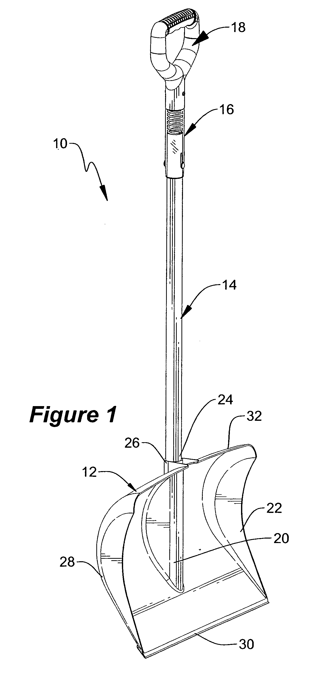
[0015] The present invention provides a lightweight shovel with a large scoop type blade, a plastic coated metal handle and a compact shock absorbing cartridge located between the distal end of the metal handle and a D-shaped handgrip so as to not interfere with the operation of the shovel. The construction of the shock absorbing cartridge simplifies assembly of the shock absorbing shovel while providing a non-pinching and non-binding utility. The leading edge of the blade includes a removable and replaceable shock absorbing wear member to further reduce shock incurred by a user. The blade, D-shaped handle and portions of the shock absorbing cartridge are formed of injection molded plastic having integrated connectors to cooperate with one another in an interlocking manner. Metal fasteners or connectors may be utilized to insure the components remain attached in the harshest conditions.
[0016] The device incorporates a minimum number of components by integrally forming the connectors into the injection molded components which slide together for ease of assembly, whereby assembly of the device requires minimal hardware and a minimum number of hand tools. Injection molding allows the components to be formed with a single wall having integral spines, ribs and gussets for increased rigidity. In addition, the polymeric construction prevents corrosion for an aesthetically pleasing tool.
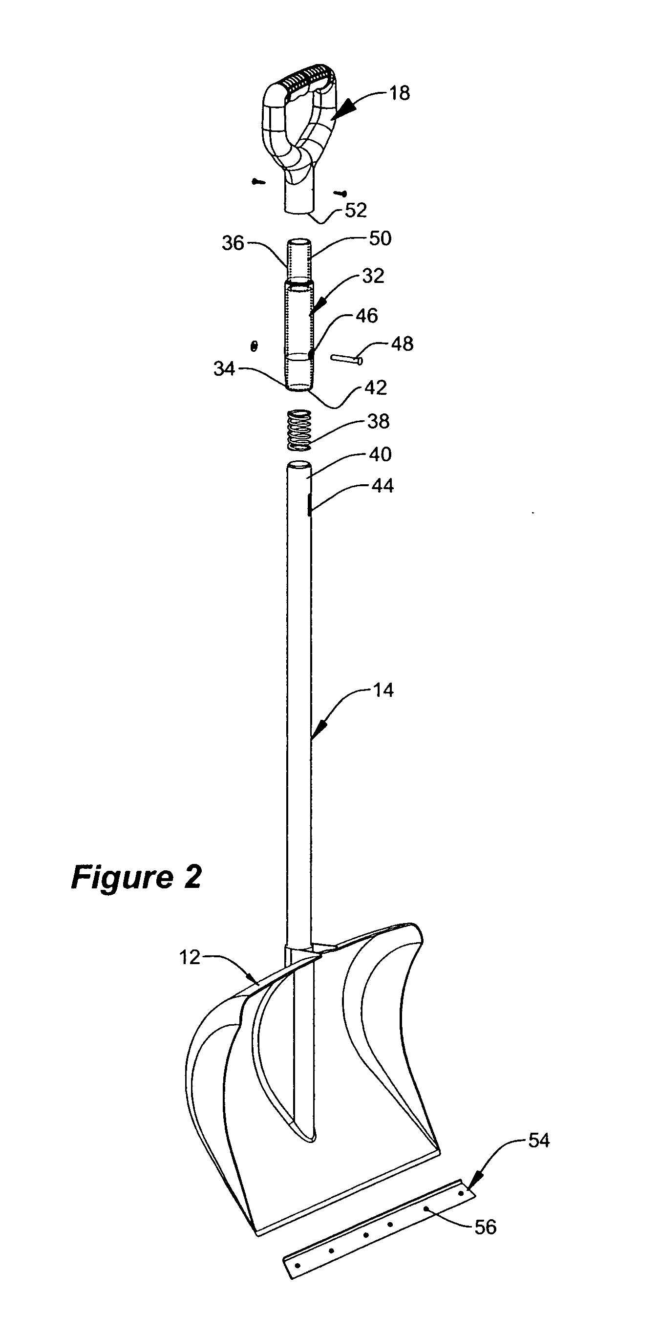
[0017] The shock absorbing cartridge includes a one-piece casing for housing the biasing member. One end of the casing includes an integrally formed outwardly projecting boss for interlocking cooperative engagement with an inwardly extending socket formed into the D-shape handgrip. A second end of the casing is constructed with an integrally formed inwardly extending socket for sliding cooperative engagement with the distal end of the elongated handle. The engagement between the bosses and the sockets serve to rigidly connect the components together into a secure shock absorbing shovel. The one piece ccasing permits the biasing member to be retained completely inside of the shock absorbing cartridge.
[0019] A further objective is to provide a shock absorbing shovel assembly having components with integrated connectors which accommodates injection molding plastic formation of the components for increased structural integrity.
[0021] Another objective is to provide a shock absorbing shovel handle having an enclosed biasing member to prevent pinching.

Problems solved by technology

This construction increases the possibility of hand pinching, as well as subjecting the moving components to dirt, debris and the like.
Such prior art devices, while working well, have not met all of the needs of manufacturers to provide a product that can be easily manufactured, packaged and shipped to the consumer.
Nor have they met the needs of consumers requiring structural integrity combined with a pleasing aesthetic appearance and ease of use.
There are also commercial considerations that must be satisfied by any viable shock absorbing tool assembly; considerations which are not entirely satisfied by state of the art products.

Method used


Image

  • Shock absorbing shovel assembly
  • Shock absorbing shovel assembly
  • Shock absorbing shovel assembly

Examples


Embodiment Construction

[0033] While the present invention is susceptible of embodiment in various forms, there is shown in the drawings and will hereinafter be described a presently preferred embodiment with the understanding that the present disclosure is to be considered an exemplification of the invention and is not intended to limit the invention to the specific embodiments illustrated.

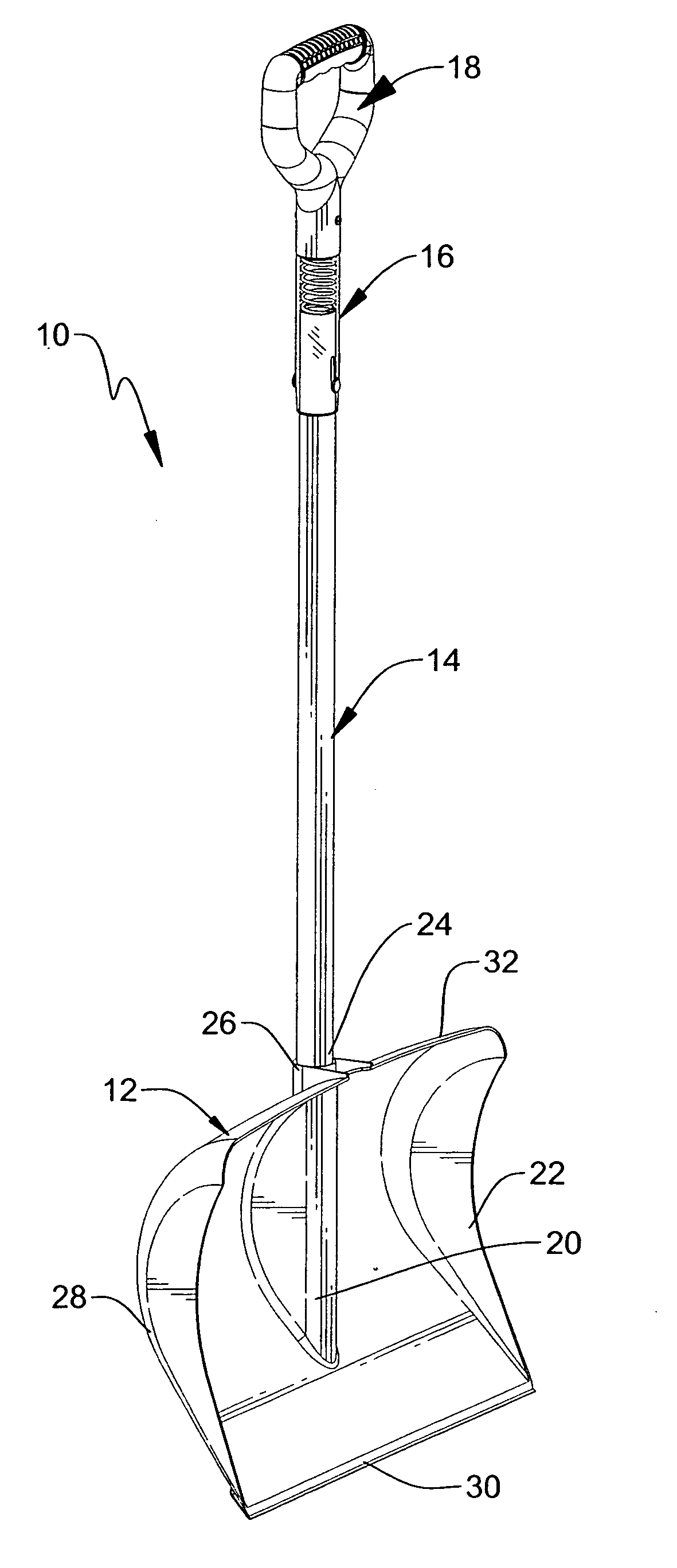
[0034]FIGS. 1-7 which are now referenced illustrate various views of the shock absorbing shovel assembly, generally referenced as 10, according to a preferred embodiment of the present invention. The shock absorbing shovel is made up of a blade 12, an elongated handle 14, a shock absorbing cartridge 16 and a handgrip 18. In the preferred embodiment the components comprising the assembly are formed of, but not limited to, a suitable plastic such as polycarbonate, polystyrene, polypropylene, polyethylene or suitable combination thereof, through the process of injection molding. The result is that the blade, shock absorbi...


PUM


Abstract

The present invention provides a lightweight shovel with a large scoop type blade, a plastic coated metal handle and a compact shock absorbing cartridge located between the distal end of the metal handle and a D-shaped handgrip so as to not interfere with the operation of the shovel.

Description

RELATED APPLICATIONS [0001] This application is a Continuation In Part of U.S. application Ser. No. 11 / 293,068 entitled Shock Absorbing Shovel Handle, the contents of which are incorporated herein in their entirety.FIELD OF THE INVENTION [0002] This invention relates generally to manual tool handles, and more specifically, to a shock absorbing shovel assembly useful for moving and scraping debris and the like. BACKGROUND INFORMATION [0003] The shovel may be one of the oldest known hand tools. The basic components of the shovel include an elongated handle and a blade. The elongated handle serves as a lever to increase force on the blade. The blade includes a load bearing plate to which the handle is connected. The load bearing plate terminates in a straight or curved edge. The handle is used to swing or rapidly push the blade into debris whereby any obstruction encountered by the blade is transmitted through the handle to the hands and arms of the user. The handle is usually made of ...

Claims


Application Information

Patent Timeline
IPC IPC(8): A01D9/00
CPCA01B1/02
Inventor ROSINE, LYLE A.ANDERSON, TORRENCE
Owner SUNCAST
Learn More