Image display unit, and method of manufacturing the same

a technology of image display unit and display unit, which is applied in the manufacture of electrode systems, discharge tube luminescnet screens, electrode systems, etc., can solve the problems of lowering the accuracy of alignment, increasing the cost of alignment apparatus, and reducing the ease of identification of marks, so as to achieve high productivity and quality, the effect of low cos

Inactive Publication Date: 2007-06-07
KK TOSHIBA
View PDF0 Cites 39 Cited by
  • Summary
  • Abstract
  • Description
  • Claims
  • Application Information

AI Technical Summary

Benefits of technology

[0009] It is an object of the present invention to provide an image display unit with high productivity and quality at low cost, and a method of manufacturing the unit.

Problems solved by technology

This increases the cost of an alignment apparatus, and decreases the mark identification easiness.
Contrarily, if a two-dimensional plane size is higher than 2 mm, the size of mark becomes too large, and a balance to a pixel size becomes bad, lowering the accuracy of alignment.
If a marking area exceeds the 6 mm diameter, an alignment mark is likely come out of a visual field of a camera, and alignment takes much time.

Method used


Image

  • Image display unit, and method of manufacturing the same
  • Image display unit, and method of manufacturing the same
  • Image display unit, and method of manufacturing the same

Examples


Embodiment Construction

[0045] Best mode of the invention will be explained hereinafter with reference to the accompanying drawings.

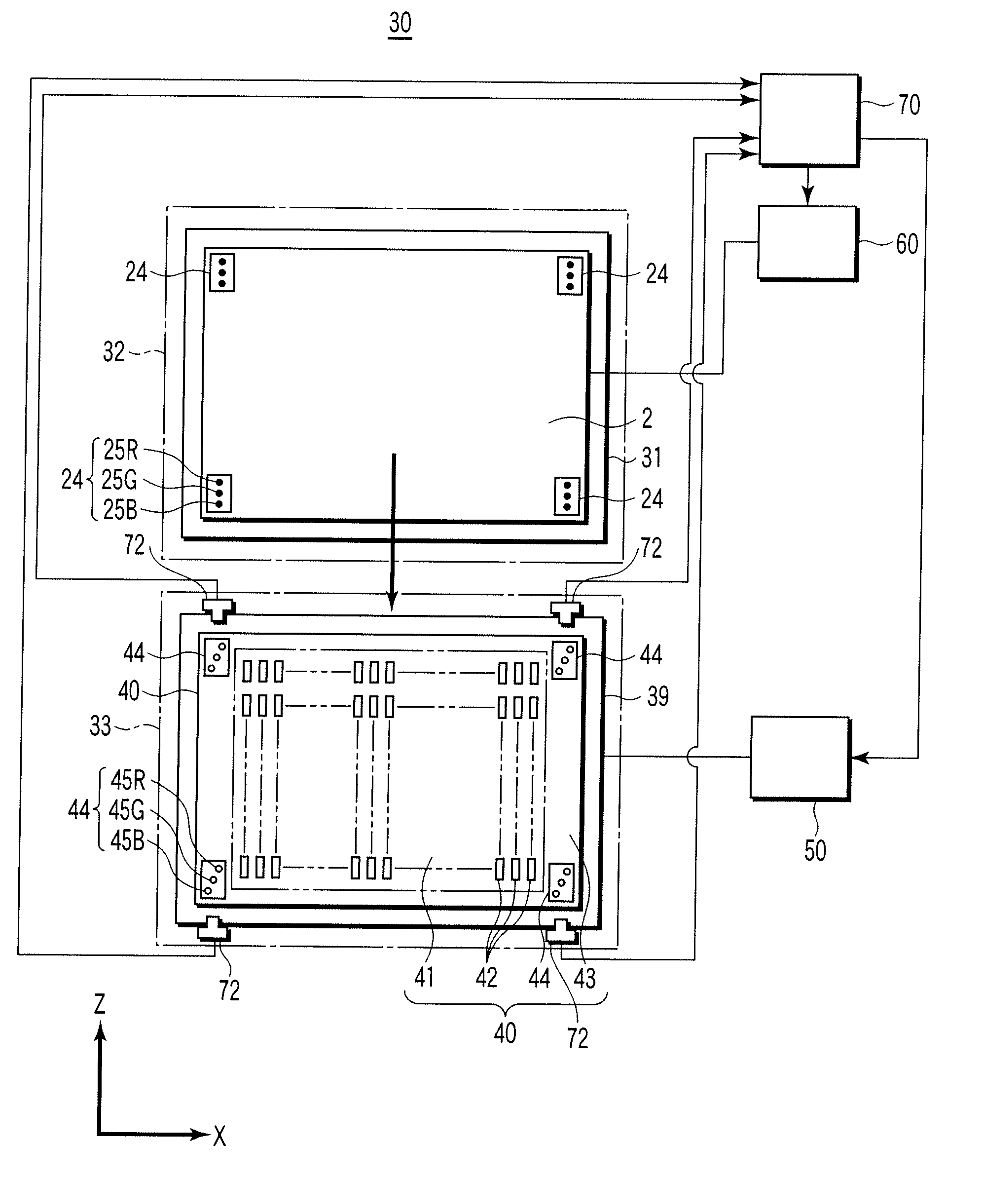
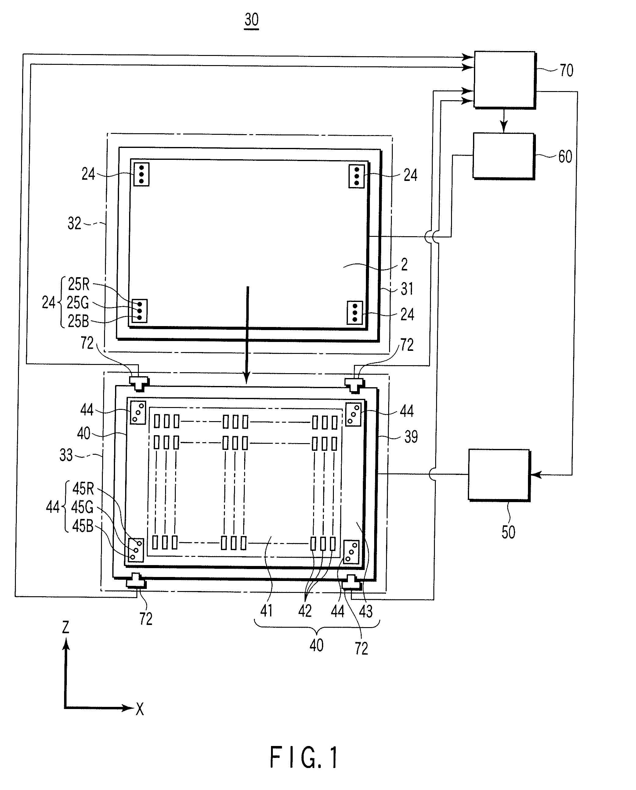
[0046] An alignment apparatus 30 used for manufacturing an image display unit of the invention has a substrate holder 31, a mask holder 39, a dry plate 40, a mask holder drive unit 50, a substrate holder drive unit 60, a controller 70, a CCD camera 72, and many other not-shown peripheral devices, as shown in FIG. 1. The alignment apparatus 30 is provided in an area from a standby unit 32 to an alignment unit 33, and a not-shown exposure unit is provided in this area or in proximity to this area.

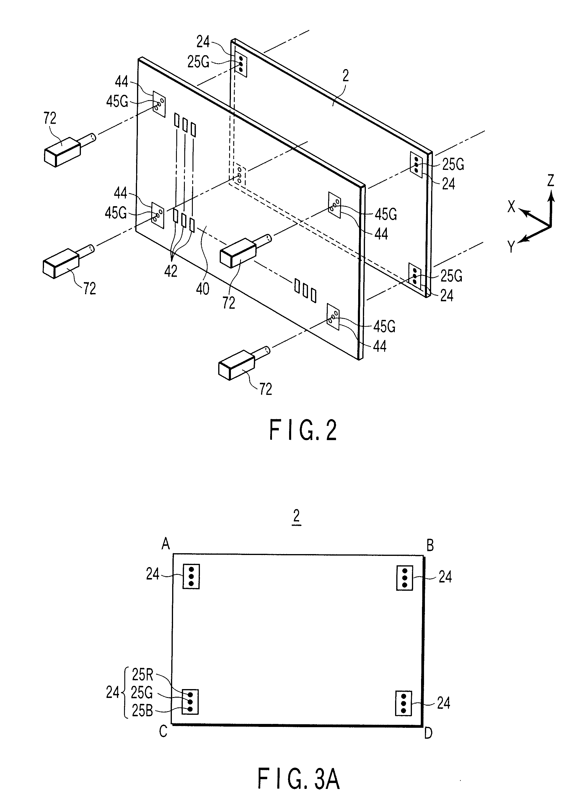
[0047] The operations of the alignment apparatus 30 and exposure unit are subject to centralized control by a controller 70. The controller 70 controls the operations of the drive units 50 and 60 and exposure unit based on an image pickup signal sent from four CCD cameras 72, and aligns an object substrate 2 to the dry plate 40. Four cameras 72 are arranged corresponding to marking ar...


PUM


Abstract

An image display unit having a back-side substrate on which a number of electron emission elements are arranged, and a front-side substrate which is opposed to a back-side substrate and has fluorescent patterns and light-shielding patterns arranged at positions corresponding to electron emission elements, wherein a marking area is provided at least two locations in an ineffective part of the inside of the front-side substrate, corresponding to alignment marks of a dry plate, and each marking area has three alignment marks. According to the present invention, it is unnecessary to change R, G, B masks whenever three color fluorescent patterns are exposed, and realignment between a mask and a substrate is unnecessary.

Description

CROSS-REFERENCE TO RELATED APPLICATIONS [0001] This is a Continuation Application of PCT Application No. PCT / JP2005 / 015161, filed Aug. 19, 2005, which was published under PCT Article 21(2) in Japanese. [0002] This application is based upon and claims the benefit of priority from prior Japanese Patent Application No. 2004-245297, filed Aug. 25, 2004, the entire contents of which are incorporated herein by reference.BACKGROUND OF THE INVENTION [0003] 1. Field of the Invention [0004] The present invention relates to a flat image display unit using an electron emission element, and a method of manufacturing the unit. [0005] 2. Description of the Related Art [0006] A flat image display unit has been developed as a next-generation image display unit in recent years. In the flat image display unit, a number of electron emission elements are arranged to be opposite to a fluorescent plane. An electron emission element is available in various types, and is basically a field emission type. A d...

Claims


Application Information

Patent Timeline
Patent Type & Authority Applications(United States)
IPC IPC(8): H01J9/38H01J63/04
CPCH01J9/2271H01J2329/00H01J9/241H01J9/261
Inventor NAKAMURA, AKIYOSHIKOZUKA, TOMOKOMIKAMI, AKIRA
Owner KK TOSHIBA
Why Eureka
Try Eureka