Regenerative braking method for vehicle having electric motor

a technology of electric motor and braking method, which is applied in the direction of braking system, motor/generator/converter stopper, dynamo-electric converter control, etc., can solve the problems of air pollution and the unfamiliar feeling of the brake pedal by the vehicle operator, and achieve the effect of the same feeling of the brake pedal

Active Publication Date: 2007-06-07
HL KLEMOVE CORP
View PDF6 Cites 26 Cited by
  • Summary
  • Abstract
  • Description
  • Claims
  • Application Information

AI Technical Summary

Benefits of technology

[0012] The present invention has been made in order to solve the above problems. It is an aspect of the invention to provide a regenerative braking method for vehicles having an electric motor, which can prevent the problem of over-braking during a regenerative braking operation and maintain the same brake pedal feeling as that of conventional vehicles.

Problems solved by technology

Conventional engine powered vehicles have several problems in that they require numerous devices, such as for example, an engine, transmission, drive shaft, hydraulic brake, fuel supply device associated with the engine, intake and exhaust devices, cooling and lubricating devices, vibration-proof device, etc.
Also, the engine powered vehicles tend to cause air pollution due to exhaust gas.
However, this may cause the vehicle operator to experience unfamiliar brake pedal feeling, and there exists a need for minimizing a bad effect thereby.

Method used


Image

  • Regenerative braking method for vehicle having electric motor
  • Regenerative braking method for vehicle having electric motor
  • Regenerative braking method for vehicle having electric motor

Examples


Embodiment Construction

[0022] Reference will now be made in detail to exemplary embodiments of the present invention, examples of which are illustrated in the accompanying drawings, wherein like reference numerals refer to like elements throughout. The embodiments are described below to explain the present invention by referring to the figures.

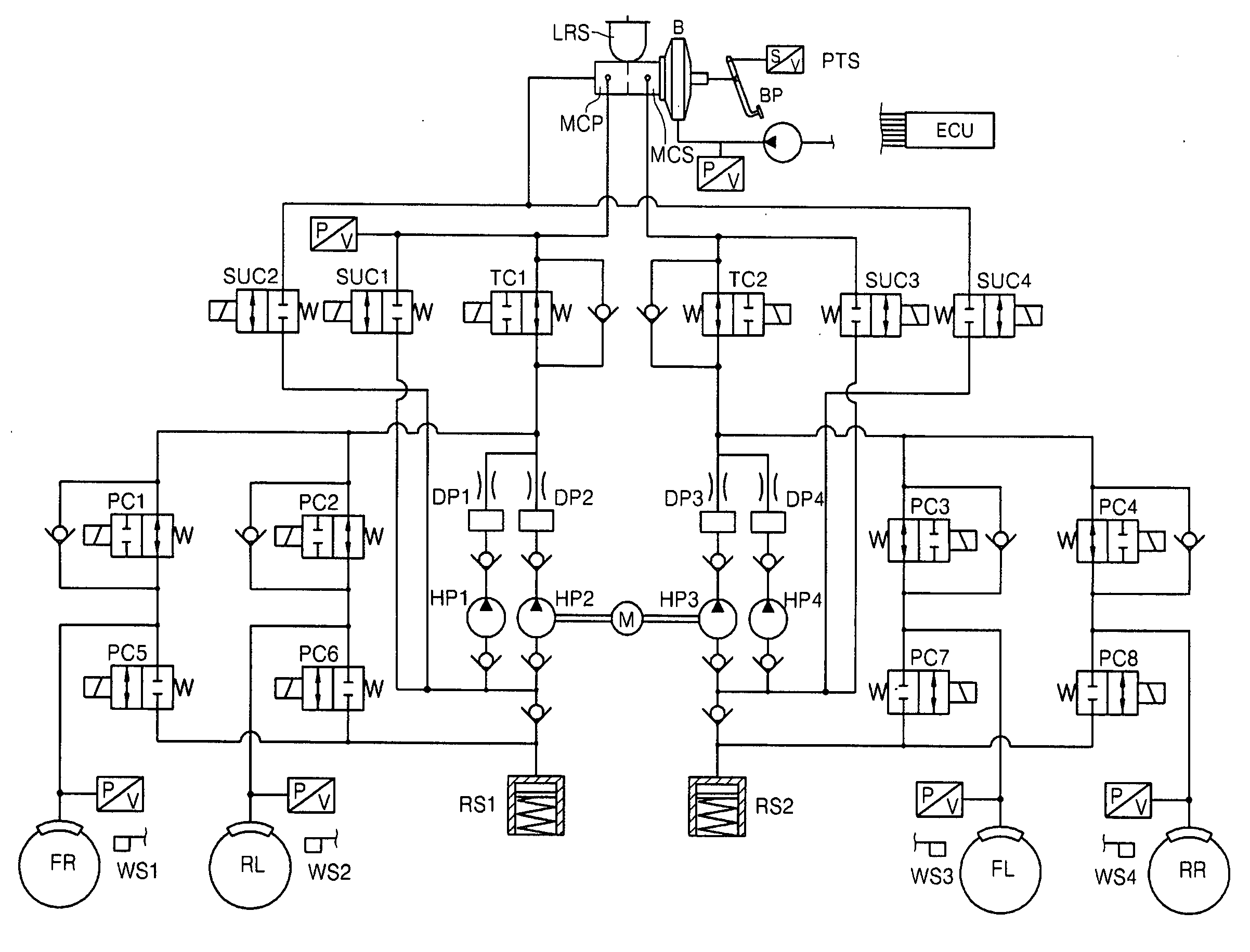
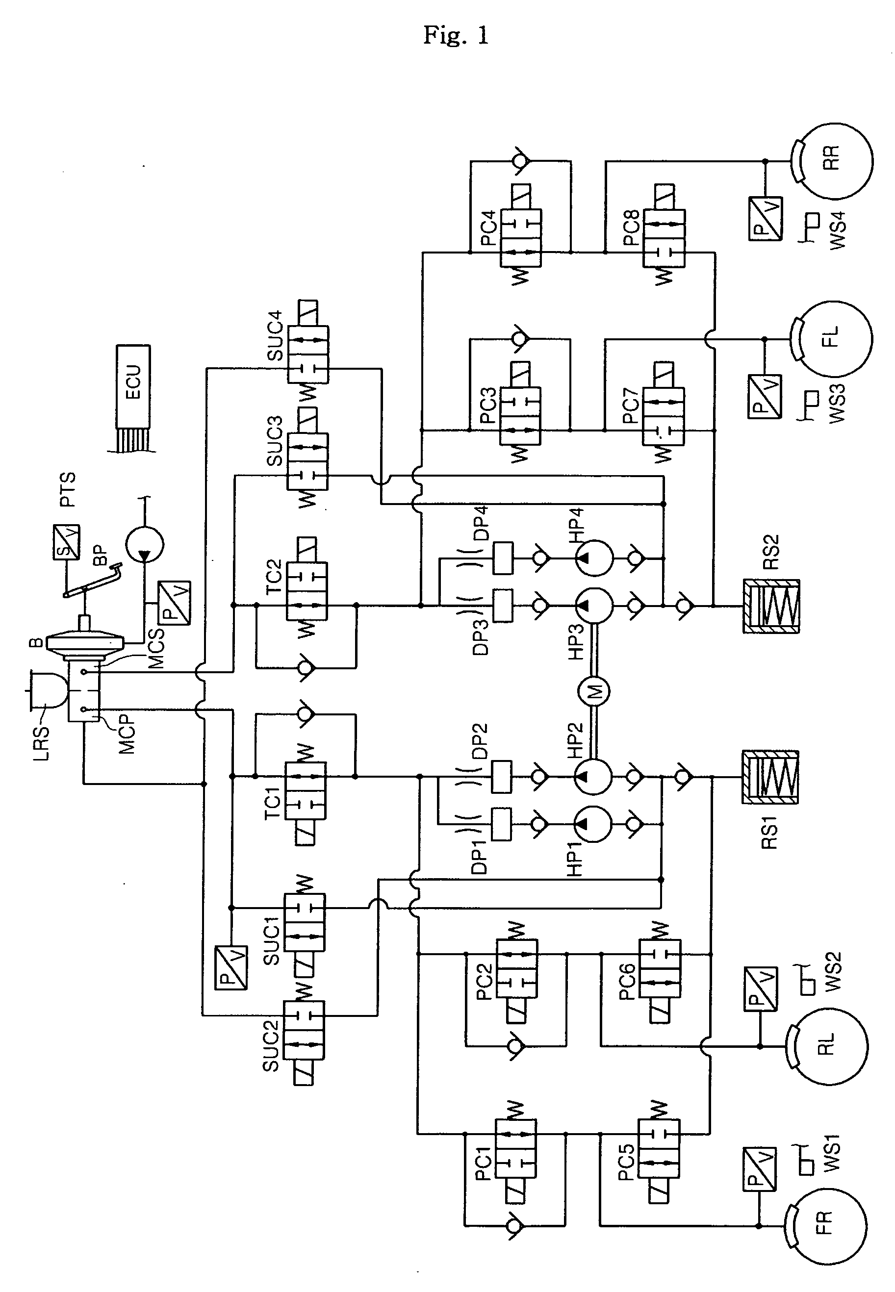
[0023]FIG. 1 is a diagram showing an electronically controlled hydraulic brake device consistent with the present invention. As shown in FIG. 1, the hydraulic brake device comprises a master cylinder MC to generate a brake pressure by operation of a booster B if a brake pedal BP is pressed.

[0024] The master cylinder MC includes two chambers MCP and MCS. Afirst one of the chambers MCP is used to control a brake hydraulic pressure to be transmitted from the master cylinder MC to wheel cylinders WFR and WRL that are installed, respectively, to a front right wheel FR and a rear left wheel RL. A normal open type cut valve TC1 is provided on a hydraulic line between the...


PUM


Abstract

A regenerative braking method for a vehicle having an electric motor. During an initial stage of a regenerative braking operation related to the vehicle having the electric motor, a flow rate of brake liquid as much as the amount of regenerative braking is delivered into a reservoir through opened exit valves of non-driving wheels, so as to generate a hydraulic braking force needed after subtracting the amount of regenerative braking from the amount of braking desired by a vehicle operator. When the amount of regenerative braking increases, exit valves of driving wheels are controlled to fulfill the total amount of braking desired by the vehicle operator. Also, when the amount of regenerative braking decreases, wheel pressures have to be increased to fulfill the vehicle operator's desire to brake. In the regenerative braking method for generating a residual amount of braking needed after subtracting the amount of regenerative braking, which corresponds to an amount generated by the electric motor, from the amount of braking desired by the vehicle operator, during the regenerative braking operation, based on a pressure difference between a pressure in the master cylinder and wheel pressures, entrance valves of the driving wheels are controlled to realize an operator's pedal feeling, and the exit valves of the driving wheels are controlled to allow the wheel pressures to follow a target pressure.

Description

CROSS-REFERENCE TO RELATED APPLICATION [0001] This application claims the benefit of Korean Patent Application No. 2005-0118533, filed on Dec. 7, 2005 in the Korean Intellectual Property Office, the disclosure of which is incorporated herein by reference. BACKGROUND OF THE INVENTION [0002] 1. Field of the Invention [0003] The present invention relates to a regenerative braking method for a vehicle having an electric motor, and, more particularly, to a regenerative braking method for a vehicle having a regenerative braking function through the use of an electric motor, in which a hydraulic brake device can be controlled in consideration of a regenerative braking force. [0004] 2. Description of the Related Art [0005] Conventional engine powered vehicles have several problems in that they require numerous devices, such as for example, an engine, transmission, drive shaft, hydraulic brake, fuel supply device associated with the engine, intake and exhaust devices, cooling and lubricating...

Claims


Application Information

Patent Timeline
Patent Type & Authority Applications(United States)
IPC IPC(8): H02P3/14
CPCB60L7/10B60L7/24B60T8/267B60T8/4072B60T8/4872B60T2270/604B60W10/08B60W10/184B60W30/18127B60L15/2009B60L2240/423B60L2250/26Y02T10/64Y02T10/72
Inventor KANG, HYOUNG JINPARK, MAN BOK
Owner HL KLEMOVE CORP
Why Eureka
Try Eureka