Method for measuring electromagnetic radiation pattern and gain of radiator using tem waveguide

a technology of electromagnetic radiation and gain, applied in the direction of transmitter monitoring, instruments, transmission monitoring, etc., can solve the problems of high maintenance fee for the standard test site, large measurement error rate, and long time consumption

Inactive Publication Date: 2007-06-07
ELECTRONICS & TELECOMM RES INST
View PDF5 Cites 11 Cited by
  • Summary
  • Abstract
  • Description
  • Claims
  • Application Information

AI Technical Summary

Benefits of technology

[0012] The method as recited in claim 1, further includes the steps of: c) measuring a power P0 received by an antenna of the radiator based on a conducted power accepted by the radiator and a reflecting coefficient of an antenna of the radiator, and obtaining a maximum radiation power density PD of a half-wave dipole antenna due to the power P0 at a predetermined distance; d) obtaining the maximum radiation power density Pmax among the estimated radiation power densities; e) obtaining a radiation gain of the radiator based on the maximum radiation power density Pmax obtained in the step d) and the maximum radiation power density PD obtained in the step d); and f) obtaining an effective radiation power based on the maximum radiation power density Pmax, wherein the maximum radiation power density PD of a half-wave dipole antenna due to the power P0 at a predetermined distance is obtained by an equation as: PD=PO·(gain⁢ ⁢of⁢ ⁢half-wave⁢ ⁢dipole⁢ ⁢antenna⁢ ⁢measured⁢ in⁢ ⁢TEM⁢ ⁢waveguide)4⁢π⁢ ⁢R2.

Problems solved by technology

However, the conventional radiation power measurement method performed in the OATS or the anechoic chamber have drawbacks that it takes much time to measure radiation from a test object because of direct measurement by antenna, a maintenance fee for the standard test site costs high, and there are a lot of measurement errors because of environmental uncertainty.
However, the conventional measuring method uses a cylindrical scanning method, and therefore, there is a drawback that a receiving field can be devaluated.
The conventional measuring method takes a long time to measure the power and a high maintenance fee.
Also, since there is reflection due to the ground plane, a measurement error is large.
In the conventional measuring method in the anechoic chamber described with reference to FIG. 4, the measurement error is small, however, it take a long time to measure the power and a high maintenance fee.

Method used


Image

  • Method for measuring electromagnetic radiation pattern and gain of radiator using tem waveguide
  • Method for measuring electromagnetic radiation pattern and gain of radiator using tem waveguide
  • Method for measuring electromagnetic radiation pattern and gain of radiator using tem waveguide

Examples


Embodiment Construction

[0024] Other objects and aspects of the invention will become apparent from the following description of the embodiments with reference to the accompanying drawings, which is set forth hereinafter.

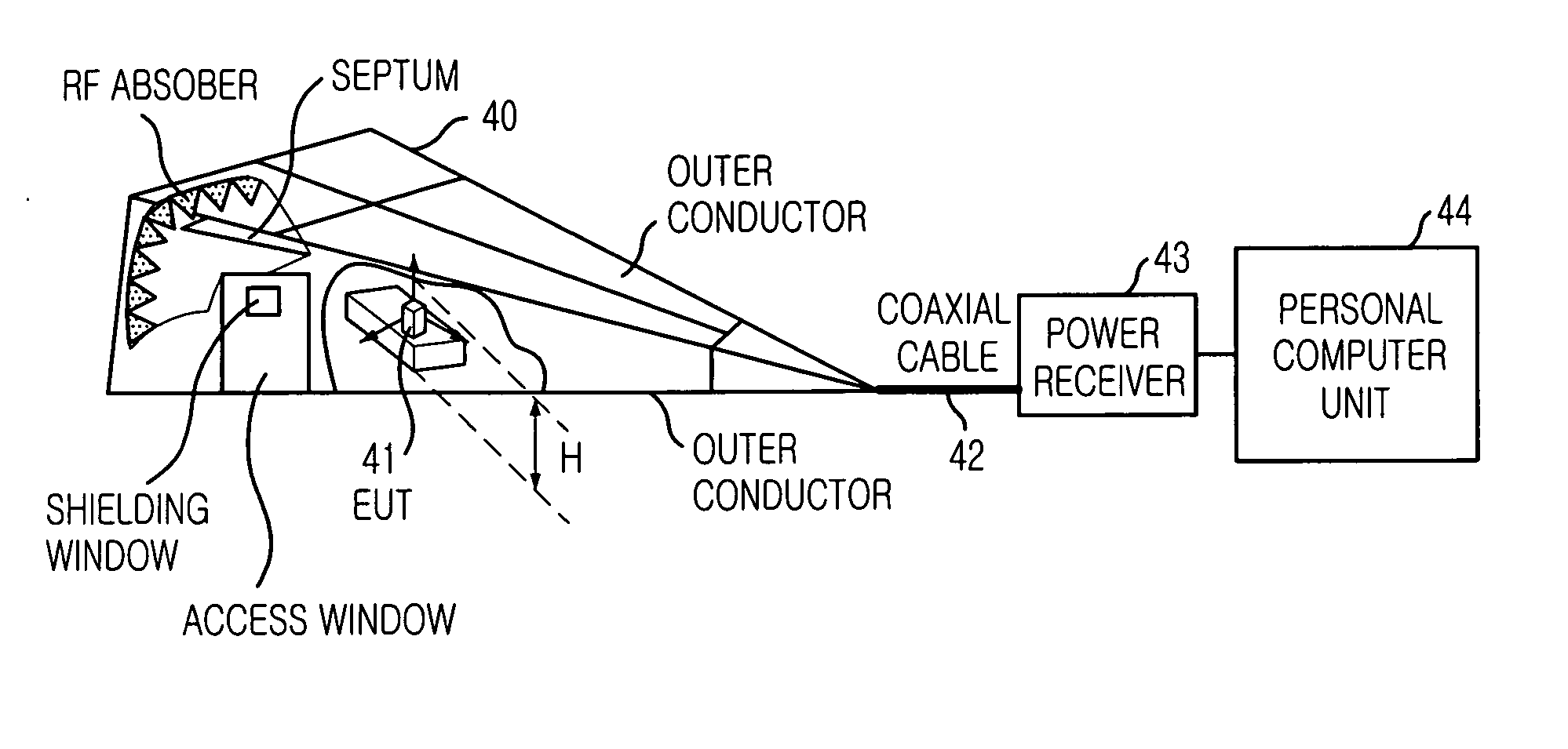
[0025]FIG. 5 is a diagram illustrating a radiation pattern and gain measurement system using TEM waveguide to which the present invention is applied.

[0026] In order to overcome problem of the conventional measuring method, for the EMI measurement, there are many tries that the measurement on the ground is replaced with measurement in transverse electric and magnetic (TEM) waveguide. Some of the measurements in TEM waveguide are standardized by international special committee on radio interference (CISPR).

[0027] The TEM waveguide means a device transferring the TEM mode, e.g., TEM cell, Gigahertz Transverse ElectroMagnetic cell (GTEM cell), and has at least one port.

[0028] In the present invention, since it is used a power of one port of the TEM waveguide, and a various kinds of TEM wav...


PUM


Abstract

A method for measuring electromagnetic radiation pattern and gain of radiator using TEM waveguide is disclosed. The method includes the steps of: a) measuring powers of output port of a transverse electric and magnetic (TEM) waveguide by changing arrangements of the radiator located within the TEM waveguide; and b) estimating a radiation power density of the radiator in free space, wherein the radiator is modeled as a dipole moment based on the powers of the output port of the TEM waveguide.

Description

TECHNICAL FIELD [0001] The present invention relates to a method for measuring an electromagnetic radiation pattern and gain of a radiator; and, more particularly, to a method for measuring the electromagnetic radiation pattern and gain of a radiator by electrically modeling the radiator based on powers of output ports of a traverse electric and magnetic (TEM) waveguide wherein the powers are measured for eighteen (18) arrangements of the radiator after locating the radiator within the TEM waveguide. BACKGROUND ART [0002]FIGS. 1 and 2 are diagrams illustrating a conventional radiation power measurement method wherein an electromagnetic signal is directly received from an antenna in an open area test site (OATS) or an anechoic chamber. [0003] As shown, a maximum radiation power or an effective radiation power (ERP) is measured in a standard test site, e.g., an open area test sites (OATS) or an anechoic chamber. The conventional radiation power measurement method will be described. [0...

Claims


Application Information

Patent Timeline
Patent Type & Authority Applications(United States)
IPC IPC(8): G01R31/00G01R29/08
CPCG01R29/0828H04B17/101H04B17/15H04B17/103H04B17/102G01R29/08
Inventor LEE, AE-KYOUNGCHOI, HYUNG-DOPACK, JEONG-KI
Owner ELECTRONICS & TELECOMM RES INST
Why Eureka
Try Eureka