Imaging apparatus

Active Publication Date: 2007-06-07
RICOH KK
View PDF7 Cites 16 Cited by
  • Summary
  • Abstract
  • Description
  • Claims
  • Application Information

AI Technical Summary

Benefits of technology

[0006] In one aspect of the present invention, an imaging apparatus is provided that is adapted to prevent a motion transmitting element such as a timing belt for driving the

Problems solved by technology

However, it has been quite difficult to prevent backlash of the carrier during scanning operations in a c

Method used


Image

  • Imaging apparatus
  • Imaging apparatus
  • Imaging apparatus

Examples


Example

First Embodiment

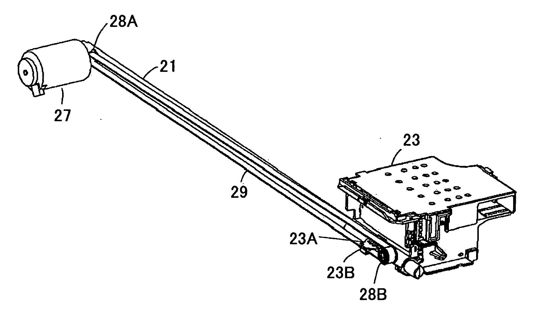
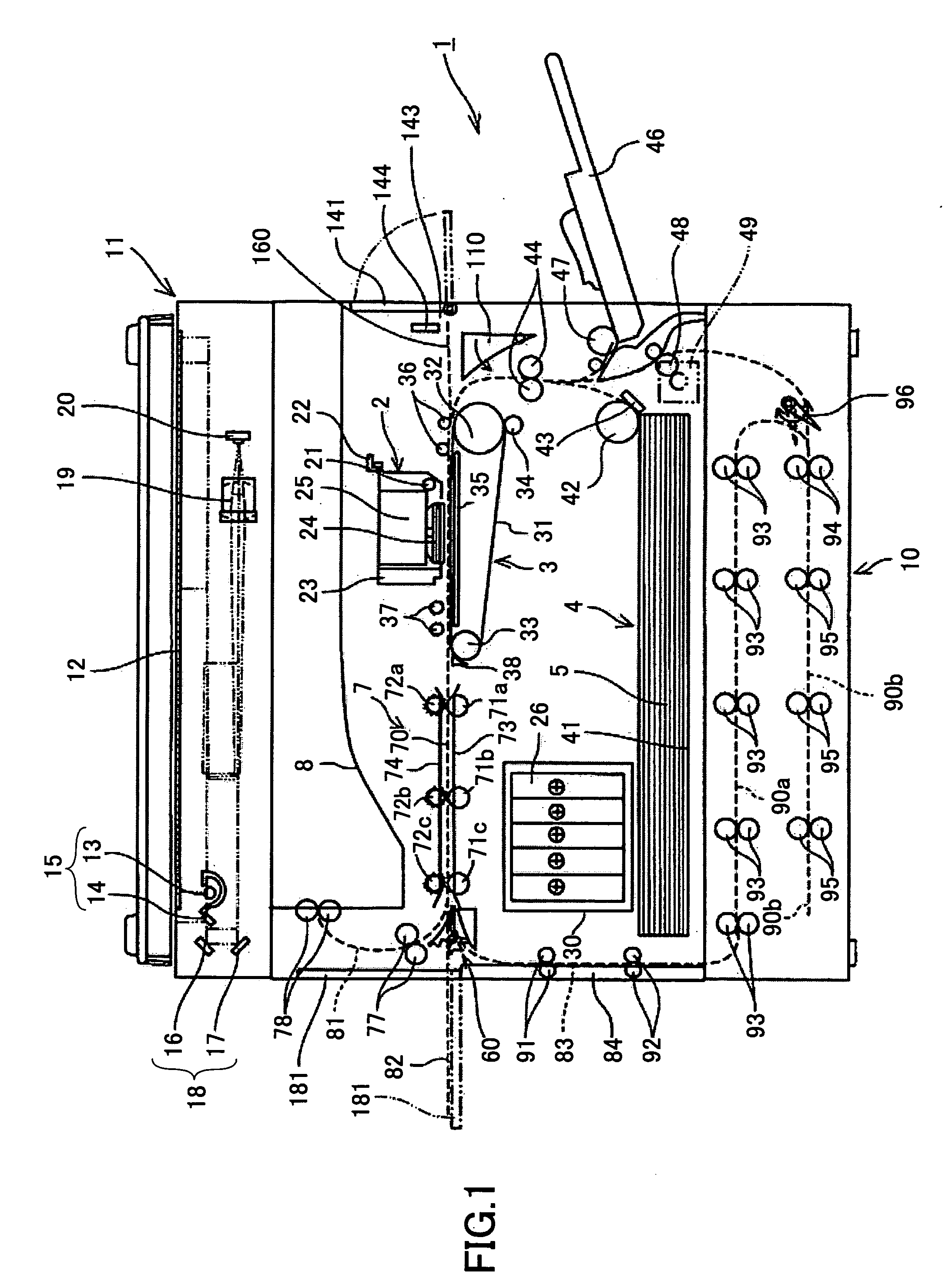
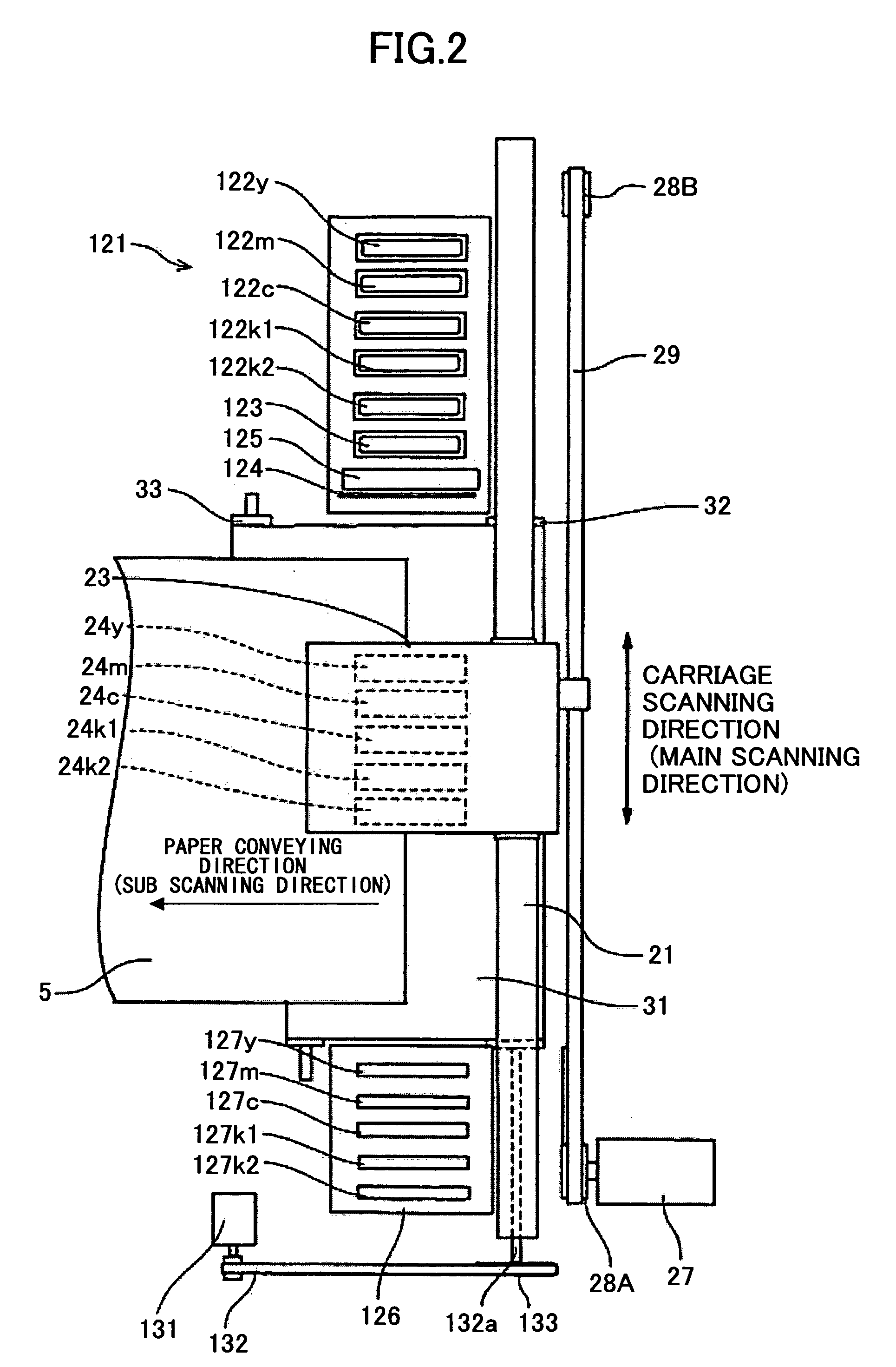
[0040]FIG. 1 is a diagram showing a general configuration of an inkjet recording apparatus as an imaging apparatus according to an embodiment of the present invention. FIG. 2 is a plan view of an image forming unit and a sub scanning conveying unit of the inkjet recording apparatus shown in FIG. 1.

[0041] The inkjet recording apparatus of the present embodiment includes a main frame 1 inside which an image forming unit 2, a sub scanning conveying unit 3, and a paper feed unit 4 are arranged. The image forming unit 2 is configured to form an image on paper 5 that is conveyed by the sub scanning conveying unit 3. The sub scanning conveying unit 3 is configured to convey the paper 5 so that it moves facing the image forming unit 2. The paper feed unit 4 is arranged at the bottom portion of the main frame 1 and includes a paper feed cassette 41. In this inkjet recording apparatus, paper 5 is fed from the paper feed unit 4 to the sub scanning conveying unit 3 one sheet a...

Example

Second Embodiment

[0069]FIG. 4 is a diagram showing a modified configuration of the coupling portion 23A for coupling the carriage 23 to the timing belt 29 according to a second embodiment of the present invention. The coupling portion 23A according to the present embodiment has two triangular plates extending from the carriage 23 to cover the upper and lower faces of the timing belt 29, and a pin 23C that penetrates through the tip portions of the two triangular plates and the timing belt 29 to fix the carriage 23 to the timing belt 29. It is noted that the pin 23C does not necessarily have to penetrate through the timing belt 29 as long as the timing belt 29 may be adequately fixed by the pin 23C. Other features of the second embodiment may be identical to those of the first embodiment, and therefore, their descriptions are omitted.

Example

Third Embodiment

[0070]FIG. 5 is a diagram illustrating another modified configuration of the coupling portion 23A for coupling the carriage 23 to the timing belt 29 according to a third embodiment of the present invention. The coupling portion 23A according to the present embodiment has two triangular plates extending from the carriage 23 to cover the upper and lower faces of the timing belt 29, and a clip-shaped plate spring 23D that engages the tip portions of the triangular plates to fix the carriage 23 to the timing belt 29. It is noted that other features of the third embodiment may be identical to those of the first embodiment, and therefore, their descriptions are omitted.


PUM


Abstract

An imaging apparatus is disclosed that includes a carriage that moves back and forth along the main scanning direction, plural recording heads mounted on the carriage that discharge recording liquid, a guide that guides the carriage in the main scanning direction, a power source and a drive pulley that drive the carriage to move in the main scanning direction, a driven pulley that transmits the drive power from the power source to the carriage, and a motion transmitting element that is arranged over the drive pulley and the driven pulley. The carriage is forced toward the guide by a tension generated by deflecting an extending direction of the motion transmitting element.

Description

BACKGROUND OF THE INVENTION [0001] 1. Field of the Invention [0002] The present invention relates to an imaging apparatus such as an inkjet recording apparatus. [0003] 2. Description of the Related Art [0004] An imaging apparatus may include a carriage that moves back and forth along the main scanning direction, plural recording heads arranged on the carriage that discharge ink, a guide member that guides the carriage in the main scanning direction, a power source for enabling the carriage to move in the main scanning direction, and a driven pulley and belt (or wire) for transmitting a drive force from the power source to the carriage. In such an imaging apparatus, imaging quality may be improved by preventing backlash of the carriage while it is being moved (i.e., while scanning operations are performed). [0005] However, it has been quite difficult to prevent backlash of the carrier during scanning operations in a conventional imaging apparatus so that image quality degradation and...

Claims


Application Information

Patent Timeline
IPC IPC(8): B41J23/00
CPCB41J19/20
Inventor NARUSE, SHINICHIRO
Owner RICOH KK
Why Eureka
Try Eureka