Belt drive controller and image forming apparatus provided with same

a technology of drive controller and drive plate, which is applied in the direction of thin material processing, printing, article separation, etc., can solve the problems of poor accuracy resulting from the shift in the impact position of ink droplets on the recording material, the inability of the conveyor belt to achieve even higher accuracy, and the inability to accurately control the stopping position of the bel

Inactive Publication Date: 2007-06-07
RICOH KK
View PDF23 Cites 58 Cited by
  • Summary
  • Abstract
  • Description
  • Claims
  • Application Information

AI Technical Summary

Benefits of technology

[0014] In consideration of the above-mentioned problems, an object of the present invention is to provide a belt drive controller capable of accurately controlling each belt stopping position during intermittent movement of a belt, and an image forming apparatus provided therewith.

Problems solved by technology

Although bleeding on to the recording material has decreased considerably as a result of increasing the viscosity of the ink, poor accuracy resulting from shifts in the impact position of the ink droplets on the recording material is readily apparent visually in the form white lines, black lines and banding.
Consequently, controlling each belt stopping position during intermittent movement of the conveyor belt to attain even higher accuracy has become an important technical issue.
However, conventional methods for controlling driving as described in the above-mentioned Japanese Patent Application Laid-open No. 2001-248822 had the problem of being unable to control each belt stopping position during intermittent movement of the conveyor belt with sufficiently high accuracy so as to be able to adequately suppress deterioration of image quality in the form of white lines, black lines and banding.
A first cause of being unable to control each belt stopping position with sufficiently high accuracy during intermittent movement of the conveyor belt is fluctuation during belt driving in the distance from the roller surface to the belt pitch line, namely the pitch line distance (PLD), at the portion of the belt wound around the drive roller (driving supporting rotating body).
For this reason, the belt stopping position during intermittent movement of the conveyor belt ends up shifting from the target position, and each belt stopping position cannot be controlled accurately during intermittent movement of the conveyor belt.
In addition, a second cause of being unable to accurately control each belt stopping position during intermittent movement of the conveyor belt is detection error attributable to the encoder or other detection means.
In the case of detecting a single rotation angular displacement or rotation angular velocity of a supporting roller around which a conveyor belt is wrapped, and controlling driving based on that detection result, an error occurs between the belt movement distance obtained from the detection result and the actual belt movement distance due to eccentricity of the supporting roller and the assembly accuracy of the detection means with respect to that supporting roller.
If driving is controlled based on a detection result which contains this type of error, the belt stopping position during intermittent movement of the conveyor belt ends up shifting from the target position, thereby preventing accurate control of each belt stopping position during intermittent movement of the conveyor belt.
In addition, a third cause of being unable to accurately control each belt stopping position during intermittent movement of the conveyor belt is a change in the diameter of a supporting roller attributable to temperature changes, wear over time and so on.
As a result, even if the drive roller is rotated by the same rotation angle during each movement of the conveyor belt during intermittent transport of the recording material, the distance the recording material is transported ends up differing each time, thereby preventing accurate control of each belt stopping position during intermittent movement of the conveyor belt.
In addition, if the diameter of a driven roller provided with detection means changes, a result is obtained which is different from the distance the belt has actually moved even in the case of a detection result for the same rotation angle, thereby resulting in detection error.
Accordingly, if driving is controlled based on a detection result which contains this type of error, the belt stopping positions during intermittent movement of the conveyor belt end up shifting from the target position, and each belt stopping position during intermittent movement of the conveyor belt cannot be accurately controlled.
Furthermore, the above-mentioned problems of the prior art are not limited to driving control which intermittently moves a belt used as a recording material transport member which supports and transports a recording material, but also can similarly occur for all types of driving control of a belt which is moved intermittently.

Method used


Image

  • Belt drive controller and image forming apparatus provided with same
  • Belt drive controller and image forming apparatus provided with same
  • Belt drive controller and image forming apparatus provided with same

Examples


Embodiment Construction

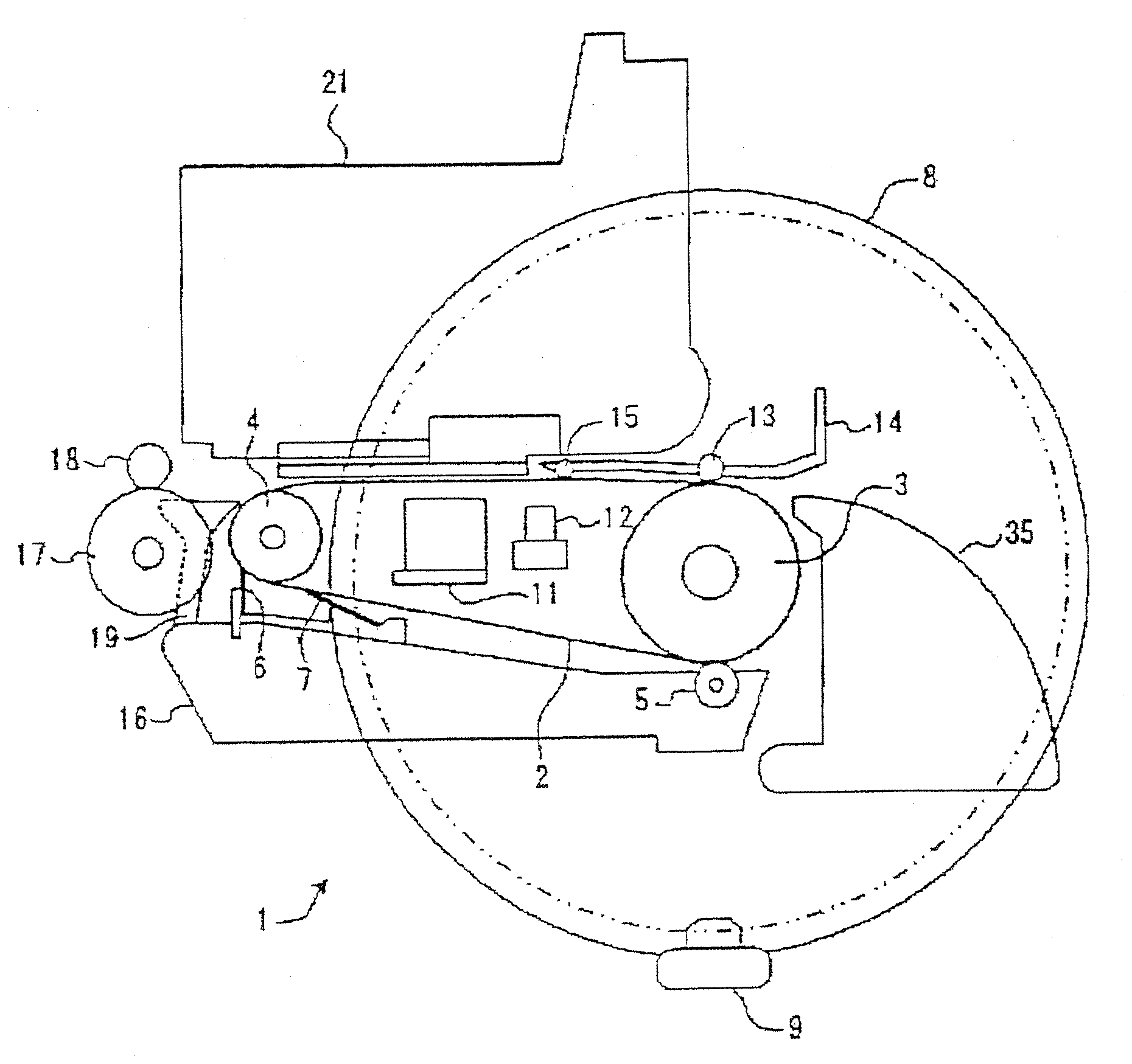
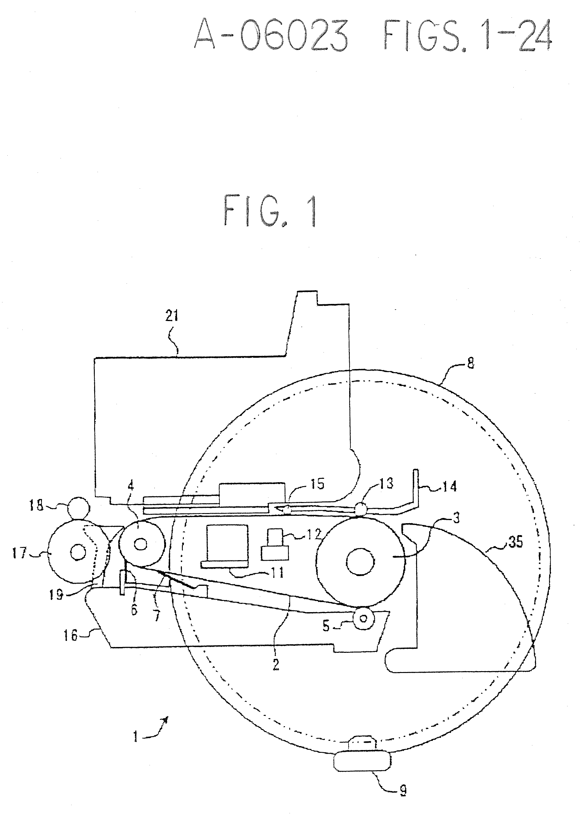
[0043] The following provides an explanation of an embodiment of the present invention applied to an image forming apparatus in the form of an ink jet recording apparatus.

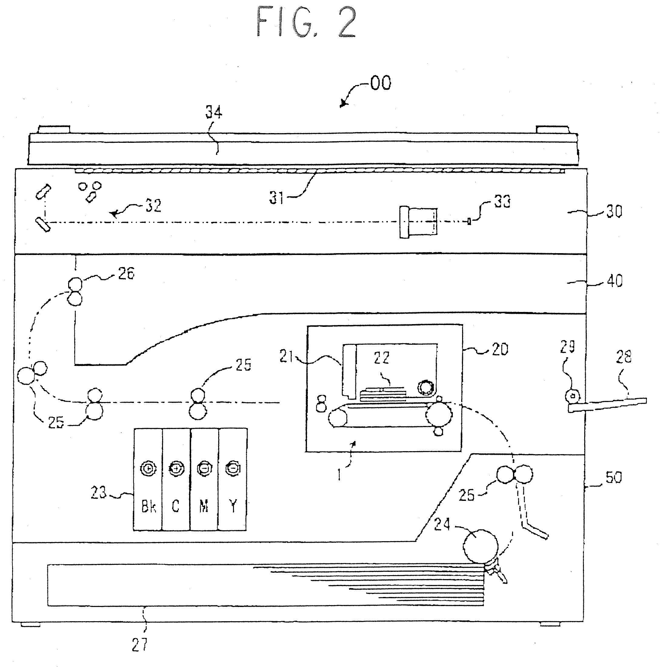
[0044]FIG. 2 shows the cross-sectional constitution of an example of an ink jet recording apparatus as claimed in the present embodiment.

[0045] This ink jet recording apparatus has a scanner unit 30 arranged above a printer unit 50, and is composed in the form of a photocopying apparatus. A paper discharge unit 40 is formed between the scanner unit 30 and the paper discharge unit 50. The scanner unit 30 has scanning means 32 capable of traveling downward below a contact glass 31, and reflected light from a document illuminated by a light source is guided to a CCD 33 by means of mirrors, lenses and so forth where the document image is read. A pressure plate 34 is provided while being able to be opened and closed above the contact glass 31. In addition, the printer unit 50 has a recording paper transport path (indi...


PUM


Abstract

A belt drive controller for controlling each belt stopping position with high accuracy during intermittent movement of a belt. This belt drive controller controls driving of a belt to intermittently move a belt wrapped around a plurality of supporting rollers including a driven roller and a drive roller. This controller detects a rotation angular displacement or a rotation angular velocity of two supporting rollers having mutually different diameters, and controls driving of the drive roller based on the detected rotation data so that the position of the belt in the direction of movement becomes a predetermined target position.

Description

BACKGROUND OF THE INVENTION [0001] 1. Field of the Invention [0002] The present invention relates to a belt drive controller for controlling the driving of a belt so as to intermittently move an endless belt wrapped around a plurality of supporting rotating bodies, and an image forming apparatus of an ink jet recording type and so forth provided therewith. [0003] 2. Description of the Background Art [0004] A known example of this type of image forming apparatus is an ink jet recording type of image forming apparatus which forms an image on a recording material by intermittently moving a recording material transport member to repeatedly advance the recording material in steps when forming an image on a recording material supported and transported on a recording material transport member comprising an endless belt. [0005] In this type of image forming apparatus, a conveyor belt (recording material transport member) maybe used as a recording material transport mechanism. In this type o...

Claims


Application Information

Patent Timeline
Patent Type & Authority Applications(United States)
IPC IPC(8): B41J2/01
CPCB41J11/007B41J11/42
Inventor TAKAHASHI, MINORUMATSUDA, HIROMICHIIMAI, SATOSHIKOIDE, HIROSHI
Owner RICOH KK
Why Eureka
Try Eureka