Packet joining method, program, and apparatus

a technology of program and apparatus, applied in the field of packet joining methods, can solve the problems of call loss, low overall service to users, and poor audio quality of new calls but also those of existing calls, and achieve the effect of reducing audio delay and increasing the utilization efficiency of radio bandwidth

Inactive Publication Date: 2007-06-07
NEC CORP
View PDF15 Cites 10 Cited by
  • Summary
  • Abstract
  • Description
  • Claims
  • Application Information

AI Technical Summary

Benefits of technology

[0016] It is an object of the present invention to solve the above-described problems and provide a packet joining method, program, and apparatus that allow an increase in the utilization efficiency of a radio bandwidth and a reduction in audio delay.

Problems solved by technology

When permission for connection of a new call is projected to degrade not only the audio quality of the new call but also those of existing calls, such as in a situation where the radio bandwidth has no room, the resource manager denies a request for connection of a new call and treats it as a call loss.
However, if a call loss frequently occurs, the overall service to users lowers.
However, the conventional method does not adopt as a selection factor the call status of a candidate audio terminal for a joining destination.
The conventional method also does not adopt as a selection factor the wireless transmission rate of a joining candidate audio terminal in a wireless LAN.
Accordingly, if a terminal as a joining source connects to an audio terminal with a low transmission rate, occupancy time of wireless transmission becomes longer, thus resulting in an increase in call losses.
This results in an increase in call losses.
Additionally, the conventional method does not adopt the packetization period of an audio terminal as a candidate for a joining destination as a selection factor.
In this case, there is a problem that unnecessary traffic flows in short-range radio.
Conventional techniques also do not take into consideration a wireless transmission rate at the time of selecting a joining destination.
Consequently, the bandwidth utilization efficiency of a wireless LAN may decrease.
Additionally, conventional techniques do not take into consideration a packetization period at the time of selecting a joining destination.
Accordingly, if a joining source uses a packetization period which is shorter than that of a joining destination, a packet joining waiting delay increases.
Consequently, conventional techniques may cause a packet joining waiting delay.

Method used


Image

  • Packet joining method, program, and apparatus
  • Packet joining method, program, and apparatus
  • Packet joining method, program, and apparatus

Examples


first embodiment

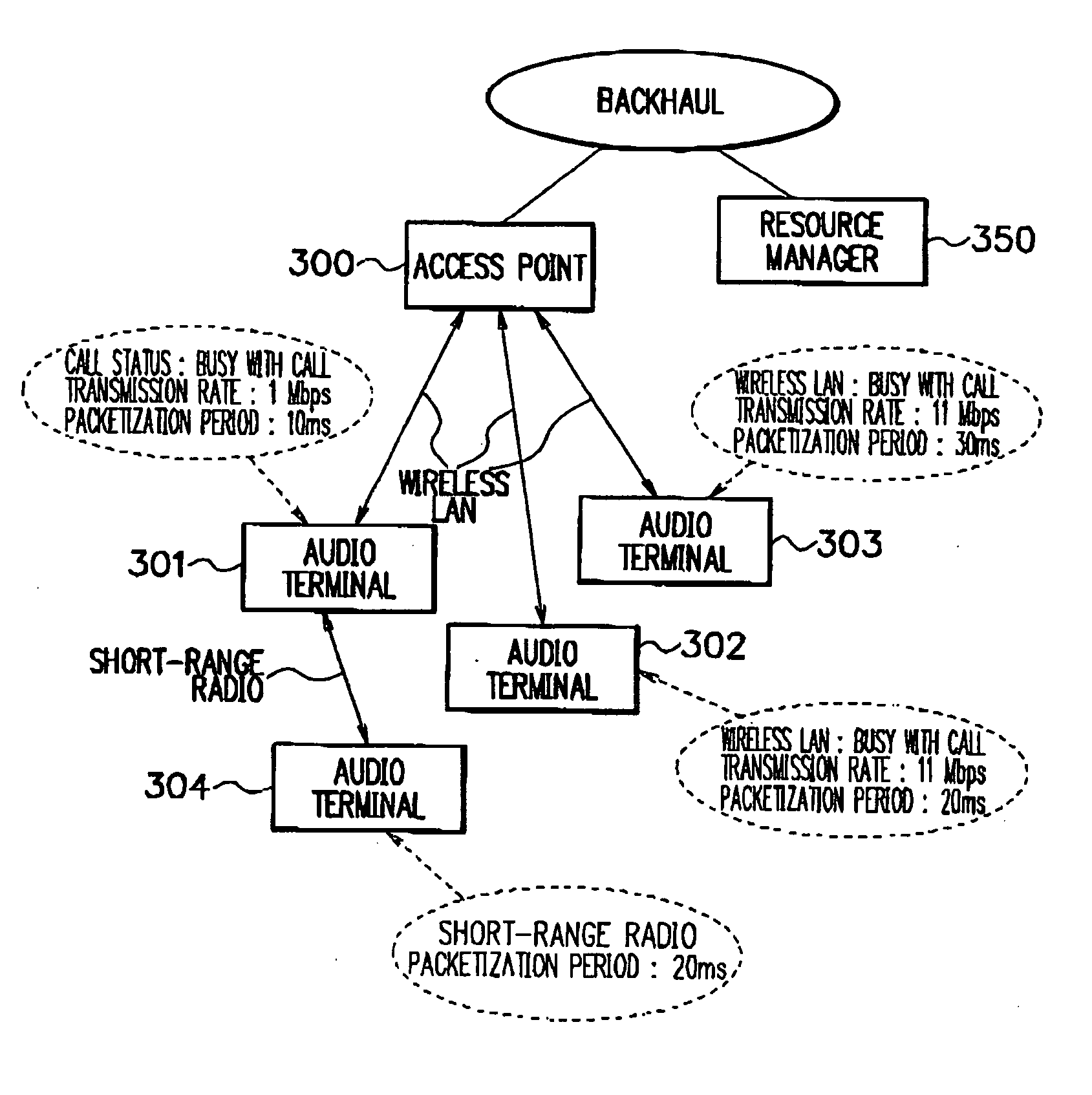
[0079] An embodiment of the present invention will be explained using FIG. 6. A network comprises an access point 300, a resource manager 350, an audio terminal 301, an audio terminal 302, an audio terminal 303, and an audio terminal 304, similarly to the above-described embodiment.

[0080] Audio terminals which are performing audio communication while connecting to the access point 300 are the audio terminal 301, audio terminal 302, and audio terminal 303. Assume that the audio terminal 304 is denied audio communication over a wireless LAN by the resource manager 350, and a call from the audio terminal 304 is lost.

[0081] The audio terminal 304 performs Neighbor Discovery using short-range radio (A1 in FIG. 9). An audio terminal having been accessed through Neighbor Discovery (B1 in FIG. 10) sends in response information including the call status, wireless transmission rate, and packetization period of the audio terminal to the audio terminal 304 having performed Neighbor Discovery,...

second embodiment

[0094] In operation as described in the above embodiment, when a call ends, an audio terminal 302 permitting a packet from an audio terminal 304 to join asks an access point 300 to delete registered information of the addresses of the joining source and joining destination and at the same time asks a resource manager 350 to release a bandwidth. At this time, the resource manager 350 can permit the audio terminal 304 as the joining source to preferentially use the bandwidth. The audio terminal 304 as the joining source detects the end of the call in the audio terminal 302 or is permitted to use the bandwidth by a resource manager. With this operation, the audio terminal 304 can be configured to continue a call by communicating an access point 300 directly by regular packet communication through a wireless LAN or by packet joining through another Neighbor Discovery process.

[0095] According to this embodiment, even if the audio terminal 302 as the joining destination ends a call, the ...

third embodiment

[0096] An embodiment which performs a packet joining process of the present invention by a computer program will be explained next.

[0097]FIG. 20 is a diagram showing the configuration of an audio terminal of this embodiment. The audio terminal comprises a wireless interface (for wireless LANs) 601, a wireless interface (for short-range radio) 602, an operation unit 609, a display unit 610, an audio I / O unit 611, a storage unit 612, and a control unit (CPU) 600. A processing program for packet joining communication and the like of the present embodiment is stored in the storage unit 612. The processing program is read from the storage unit 612 by the control unit (CPU) 600 to control the operation of the control unit (CPU) 600.

[0098] In this embodiment, the procedure for packet joining communication starting from Neighbor Discovery can be started by a user's inputting the address, telephone number, or the like of a party through the operation unit 609 and display unit 610. After co...


PUM


Abstract

There is provided a packet joining method, program, and apparatus with an increased wireless utilization efficiency and a reduced packet delay. The packet joining method includes a step of performing Neighbor Discovery within a range reachable in one hop to detect neighboring audio terminals which are connectable over short-range radio and acquiring call information including audio session information such as whether the detected audio terminals are busy with respective calls and packetization period information and wireless transmission rate information, a step of selecting one as a joining destination from the list of detected connectable audio terminals on the basis of the call information by the criteria that occupancy time of wireless transmission becomes short and that a packet delay at the time of joining becomes small, a step of requesting packet joining of the selected audio terminal as the joining destination, and a step in which an audio terminal as a joining source starts a voice cal upon receipt of a positive response from the audio terminal as the joining destination in response to the request for joining.

Description

BACKGROUND OF THE INVENTION [0001] The present invention relates to a packet joining method and, more particularly, to a packet joining method, program, and apparatus that are designed to use VoIP (Voice over Internet Protocol) in a hotspot (“HOTSPOT” is a registered trademark) system. DESCRIPTION OF RELATED ART [0002] A packet joining method of the present invention is applied to VoIP in a hotspot system expected to use an audio terminal having two interfaces, a wireless LAN interface for connection to an access point and a short-range wireless interface for connection between audio terminals. [0003] A hotspot system is a system which provides a wireless (LAN) service area where an Internet connection service is available to an unspecified number of users by setting up an access point for a wireless LAN, Bluetooth, or the like in a public place such as in a station or on the street. When VoIP is used in a hotspot system, a resource manager which manages a radio bandwidth is set up ...

Claims


Application Information

Patent Timeline
Patent Type & Authority Applications(United States)
IPC IPC(8): H04L12/28H04L12/56H04L47/43H04M3/00H04W28/00H04W40/00H04W72/04H04W74/08H04W84/10H04W84/12
CPCH04L12/2602H04L29/06027H04L41/0896H04L43/00H04L43/0882H04L47/10H04L47/14H04L47/2416H04L47/36H04W40/00H04L65/602H04L65/80H04L65/762H04L47/43H04L65/1101H04W8/04
Inventor OOKUMA, TAKAHIROYAMANO, SATORU
Owner NEC CORP
Why Eureka
Try Eureka