Programmable transceivers that are able to operate over wide frequency ranges

Inactive Publication Date: 2007-06-07
ALTERA CORP
View PDF27 Cites 12 Cited by
  • Summary
  • Abstract
  • Description
  • Claims
  • Application Information

AI Technical Summary

Benefits of technology

[0008] A PLL may be augmented with optionally usable, downstream, frequency divider circuitry to giv

Problems solved by technology

For example, the operating range of an additional PLL circuit may be relatively narrow but may cover a port

Method used


Image

  • Programmable transceivers that are able to operate over wide frequency ranges
  • Programmable transceivers that are able to operate over wide frequency ranges
  • Programmable transceivers that are able to operate over wide frequency ranges

Examples


Example

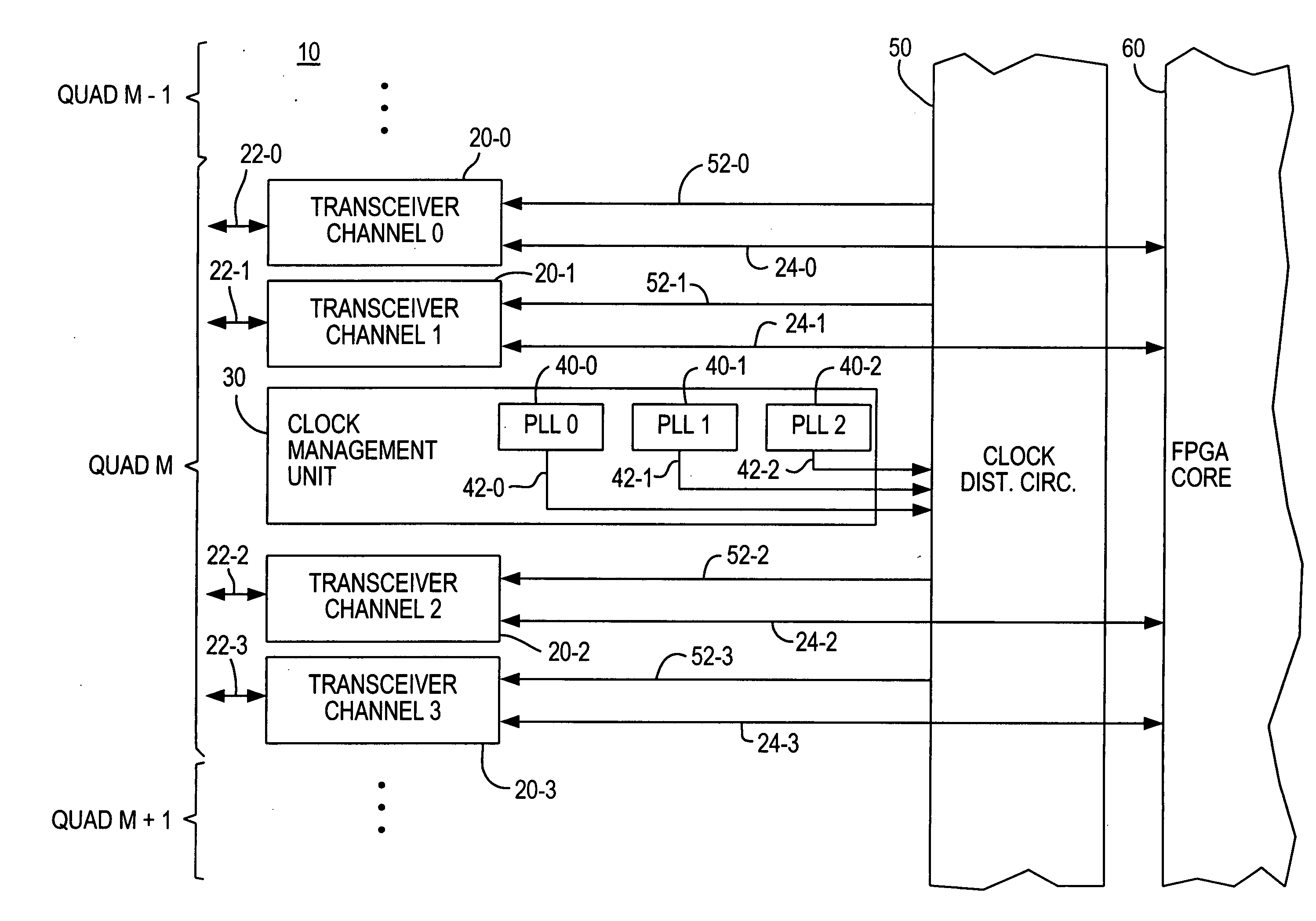
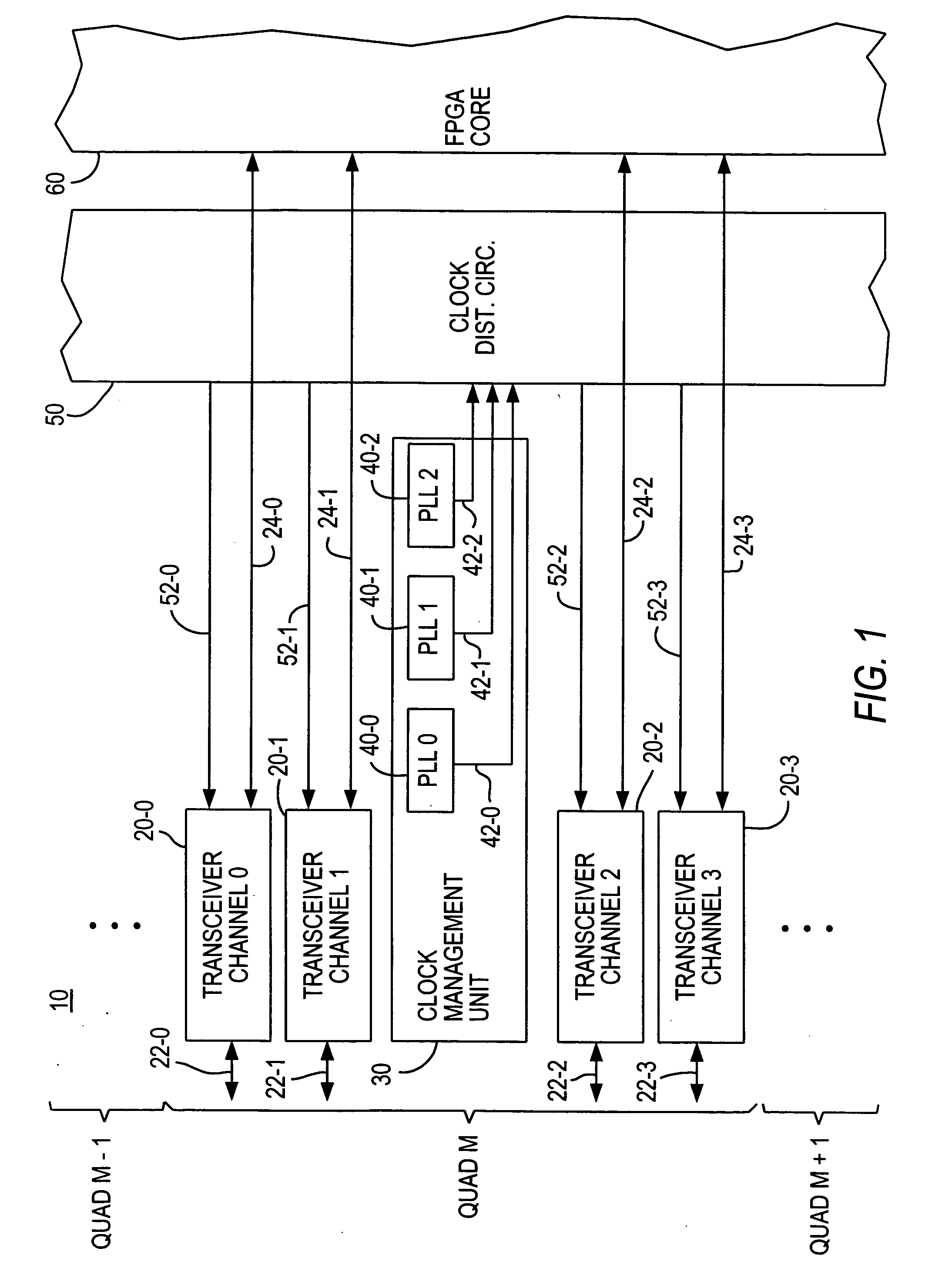
[0022] As shown in FIG. 1, illustrative FPGA 10 includes several “quads” of HSSI circuitry M−1, M, and M+1, etc. The number of such quads that may be included in any particular FPGA product is entirely optional. For example, an FPGA may include one quad, two quads, four quads, five quads, or any other desired number of quads. In the following discussion most attention will be given to quad M. It will be understood that quad M is only representative, and that other similar quads (M−1, M+1, etc.) may be included.

[0023] Quad M includes four channels of transceiver circuitry 20-0 through 20-3 and one unit of clock management circuitry 30. Circuitry 30 may also be referred to as CMU circuitry 30. Each transceiver channel 20 can handle one in-bound data stream and one out-bound data stream. The connection line 22 associated with each transceiver channel 20 in FIG. 1 may actually represent separate in-bound and out-bound data leads. Moreover, each in-bound and each out-bound data path may...


PUM


Abstract

A field-programmable gate array (“FPGA”) may include data receiver and/or transmitter circuitry that is adapted to receive and/or transmit data at any frequency(ies) or data rate(s) in a wide range of possible frequencies or data rates. Phase-locked loop (PLL) circuitry may be needed for operation of such receiver and/or transmitter circuitry. For satisfactory operation over the wide frequency range, multiple PLL circuits are provided. One of these PLL circuits may be capable of operating over the entire frequency range, possibly with better jitter performance in some portions of the range than in other portions of the range. One or more other PLL circuits may be provided that are focused on particular parts of the broad range, especially where the jitter performance of the first-mentioned PLL may not be adequate to meet some possible needs.

Description

BACKGROUND OF THE INVENTION [0001] This invention relates to field-programmable gate arrays (“FPGAs”), such as those of the type known as programmable logic devices (“PLDs”). More particularly, the invention relates to transceiver circuitry for inclusion in such devices. [0002] For convenience herein, all programmable integrated circuit devices to which the invention can be applied will be referred to as FPGAs. [0003] A frequent objective in the manufacture of FPGAs is to give the device a wide range of operating capabilities so that the FPGA can meet the various needs of many different users and thereby create a large market for the FPGA product. In general, the larger the market, the lower the unit cost the FPGA can have. On the other hand, giving an FPGA too many capabilities puts upward pressure on unit cost, so it is necessary to strike a balance between a set of capabilities that is large enough to make the product widely usable, without providing such an excess of capabilitie...

Claims


Application Information

Patent Timeline
IPC IPC(8): H03D3/24
CPCH03K19/17744H03L7/0995
Inventor SHUMARAYEV, SERGEY YURYEVICHPATEL, RAKESH
Owner ALTERA CORP
Why Eureka
Try Eureka