Oscillator

A technology of oscillating circuit and oscillating signal, applied in electric pulse generator circuit, automatic power control, pulse processing and other directions, can solve the problems of differential ring VCO loss symmetry, poor jitter performance, reduction and other problems, and achieve good jitter performance, effect of good phase noise performance

Inactive Publication Date: 2008-08-20
SONY CORP
View PDF1 Cites 10 Cited by
  • Summary
  • Abstract
  • Description
  • Claims
  • Application Information

AI Technical Summary

Problems solved by technology

The first disadvantage is the high sensitivity to changes in the voltage generated by the power supply
When the power supply voltage changes or the power supply voltage includes noise, the characteristics of the single-ended type ring VCO change substantially, which considerably deteriorates the jitter performance and phase noise performance
[0024] The second disadvantage is that there is no ability to output differential signals without providing specialized tools for outputting differential signals
The oscillation of the voltage appearing at the tail node ND3 distorts the waveform of the oscillation signal, causing the differential type ring VCO to further lose symmetry and generate oscillation with reduced amplitude
As a result, differential ring VCOs typically exhibit poor jitter performance and poor phase noise performance compared to single-ended ring VCOs

Method used


Image

  • Oscillator
  • Oscillator
  • Oscillator

Examples


Embodiment Construction

[0063] Preferred embodiments of the present invention are explained below by referring to the diagrams.

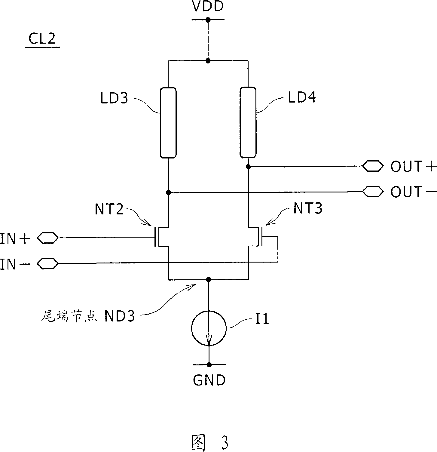
[0064] FIG. 5 is a diagram showing a typical configuration of an oscillation core of the oscillation circuit 100 according to the embodiment of the present invention. FIG. 6 is a diagram showing a typical configuration of an inverter (or inverter circuit) employed in an oscillation circuit. 7 and 8 are diagrams each showing a current source circuit for controlling a power supply current of an inverter.

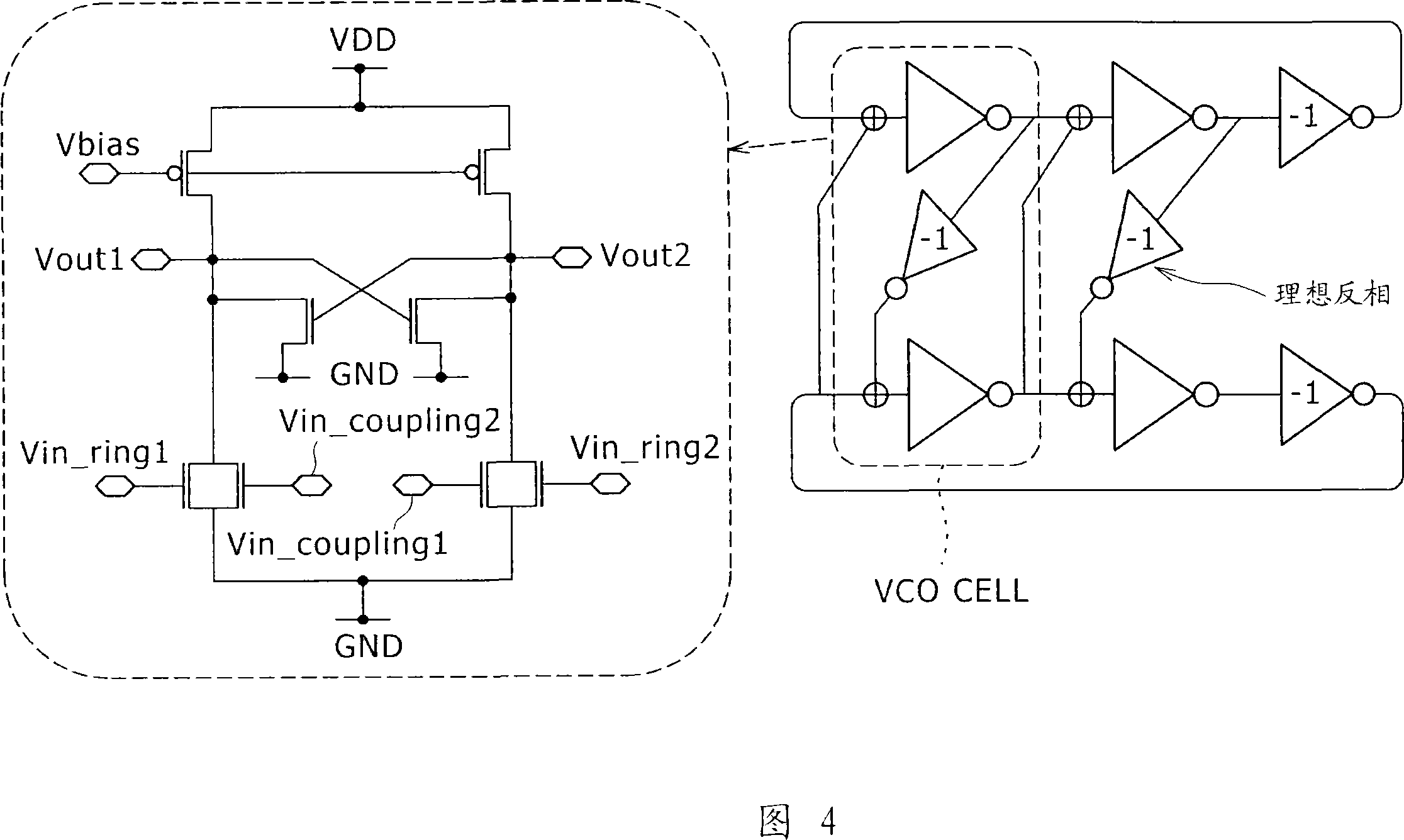
[0065] Basically, the oscillation circuit 100 is designed as a ring VCO circuit having advantages of both the single-ended type ring VCO and the differential type ring VCO.

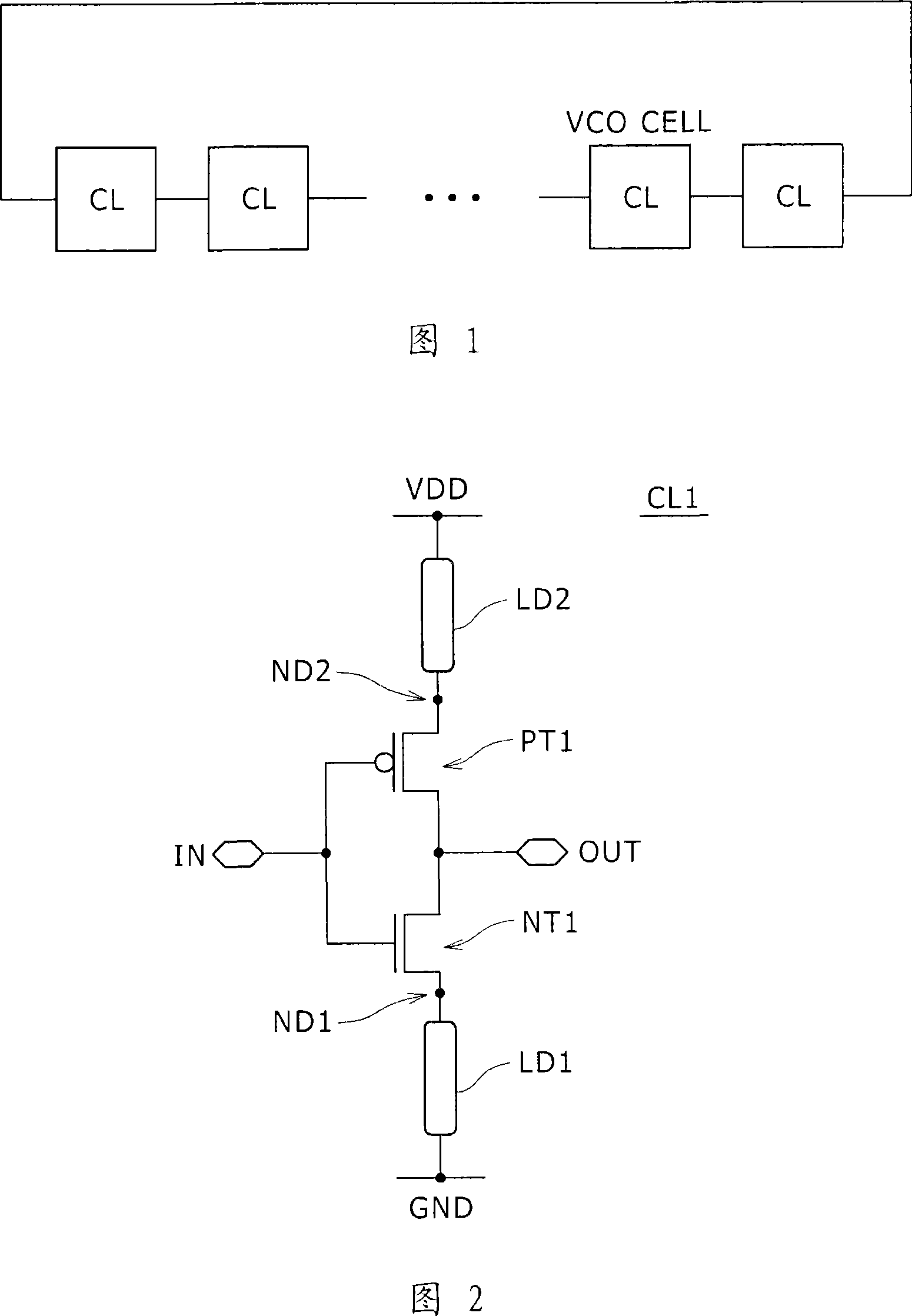
[0066] Typically, the oscillation core of the oscillation circuit 100 uses an even number of three-stage inverter rings, and each three-stage inverter ring forms a main loop. In a typical configuration shown in FIG. 5 , an oscillation circuit 100 includes first and second three-stage inverter rings ...


PUM


Abstract

The present invention provides an oscillation circuit comprising: a plurality of multi-stage inverter rings, each of which has an odd number of inverters connected in cascade with each other to form the ring through an equally odd number of nodes on the ring; a group of inverters , for connecting each node on any given one multi-level inverter ring to a corresponding one on another multi-level inverter ring in order to shift the phases of the generated oscillating signals relative to each other by a fixed difference, in order to combine this particular and other multi-stage inverter rings with each other; and a current source connected to the inverters of the multi-stage inverter ring and the inverters of the inverter group.

Description

[0001] Related Application Cross Reference [0002] The present application is related to Japanese Patent Application JP 2007-036425 filed in Japan Patent Office on February 16, 2007, the entire contents of which are hereby incorporated by reference. technical field [0003] The present invention relates to an oscillating circuit (oscillator) for generating an oscillating signal using inverters (inverting circuits) connected in a cascade manner in a loop. More specifically, the present invention relates to an oscillation circuit whose oscillation frequency (resonance frequency) can be controlled. Background technique [0004] PLL (Phase Locked Loop) circuits are widely used in applications such as generation of oscillation signals with high spectral accuracy and generation of clock signals with frequency and phase locked to data signals. Typical applications of the PLL circuit are wireless communication using a mobile phone as a main communication tool, serial communication...

Claims


Application Information

Patent Timeline
Patent Type & Authority Applications(China)
IPC IPC(8): H03K3/013H03K3/03H03K3/354H03L7/099H03K19/20
CPCH03K3/0315H03K2005/00241H03L7/0995H03K5/133
Inventor 植野洋介
Owner SONY CORP
Why Eureka
Try Eureka