
Electric arc ion plating apparatus

A technology of arc ion plating and equipment, which is applied in ion implantation plating, sputtering plating, vacuum evaporation plating, etc., and can solve the problem of protection and modification of the inner surface of long tubes and inner walls of deep hole devices and modified films or coatings Uniformity and poor binding force, etc., to reduce the content of large particles and improve the quality

Inactive Publication Date: 2012-10-31
INST OF METAL RESEARCH - CHINESE ACAD OF SCI
View PDF8 Cites 15 Cited by
  • Summary
  • Abstract
  • Description
  • Claims
  • Application Information

AI Technical Summary

Problems solved by technology

[0012] In view of the fact that the arc ion plating technology in the prior art cannot achieve the purpose of protecting and modifying the inner surface of the long tube and the inner wall of the deep hole device hole, the aperture or side length of the long tube and deep hole device that can be processed by the arc ion plating technology is improved. The depth of modification does not exceed 1:2.5, and the uniformity and bonding force of the modified film or coating are poor. The purpose of protecting and modifying the inner wall of the deep hole device hole, the deposited film or coating has good uniformity, and has a strong bond with the inner surface of the long tube and the inner wall of the deep hole device hole

Method used


Image

  • Electric arc ion plating apparatus
  • Electric arc ion plating apparatus
  • Electric arc ion plating apparatus

Examples


Embodiment 1

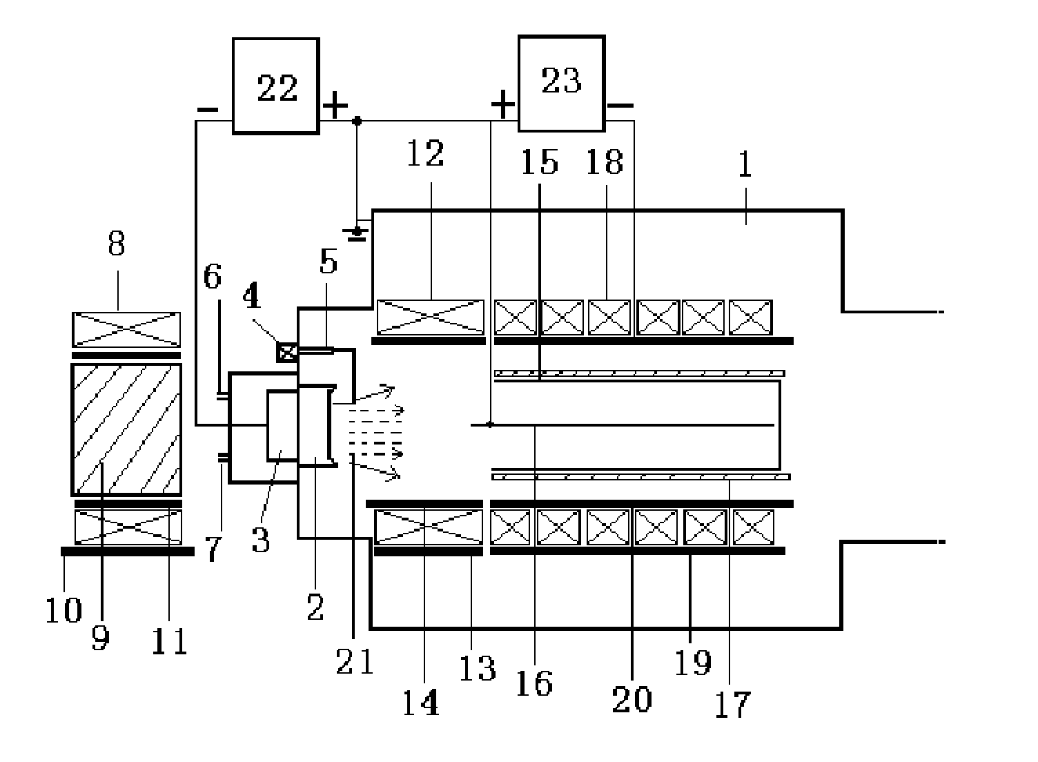
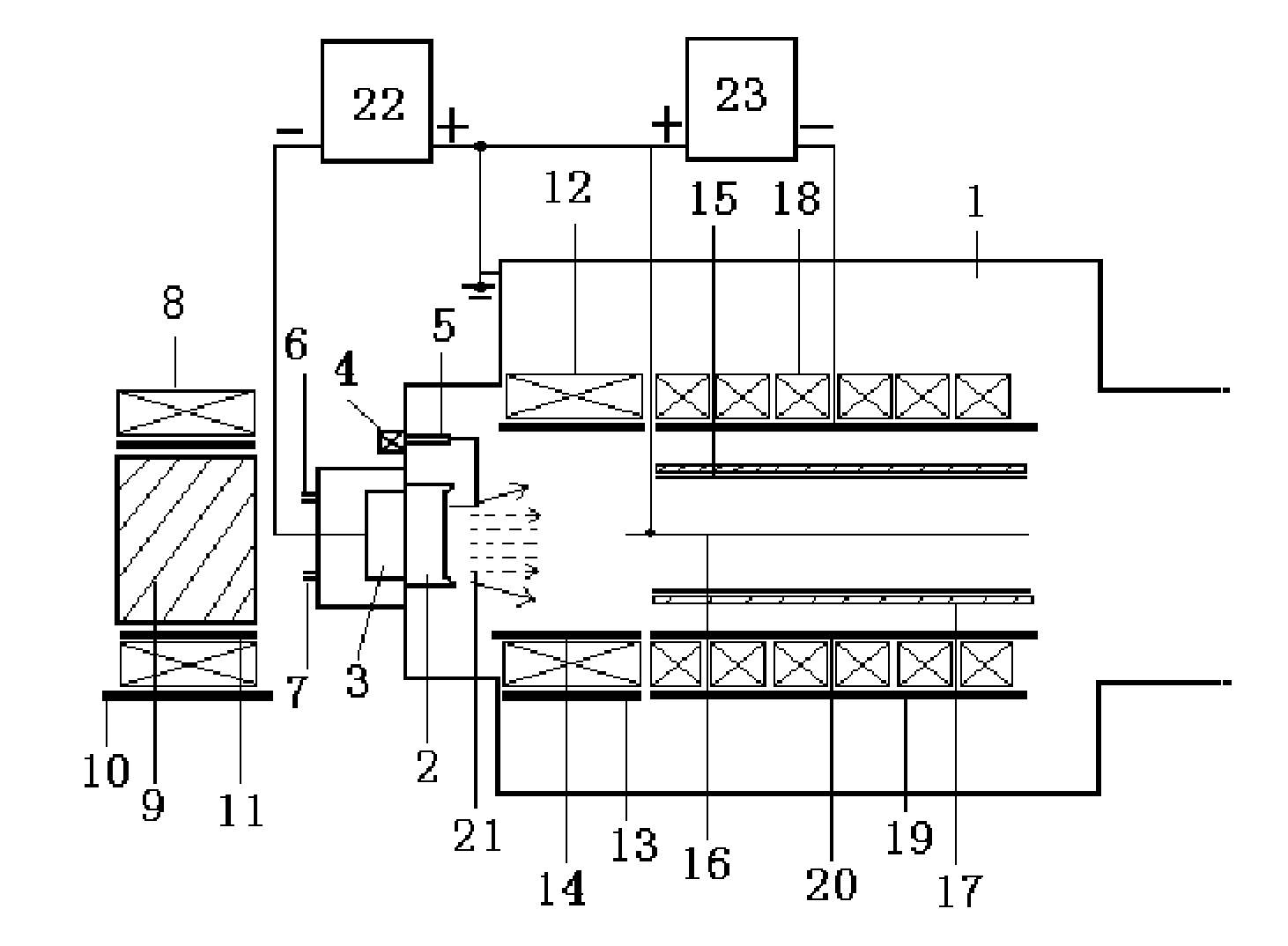
[0041] Such as figure 1 As shown, an arc ion plating equipment is provided with three sets of magnetic field generating devices, including: a first magnetic field generating device for focusing the metal ion flow emitted by the cathode target, which is arranged outside the vacuum chamber 1 The position corresponding to the back of the cathode target 2; the first magnetic field generator is the first electromagnetic coil 8 or annular permanent magnet with nickel-plated pure iron 9 installed in the middle, and the first electromagnetic coil 8 or annular permanent magnet passes through the first support cylinder 11 Or use a support frame structure to fix on the movable first workbench 10 connected to the equipment shell, the central axis of the first magnetic field generating device coincides with the central axis of the cathode target 2, and the generated magnetic induction intensity is 1000-5000Gauss, the first The inner diameter of the support tube 11 or the side length of the...

Embodiment 2

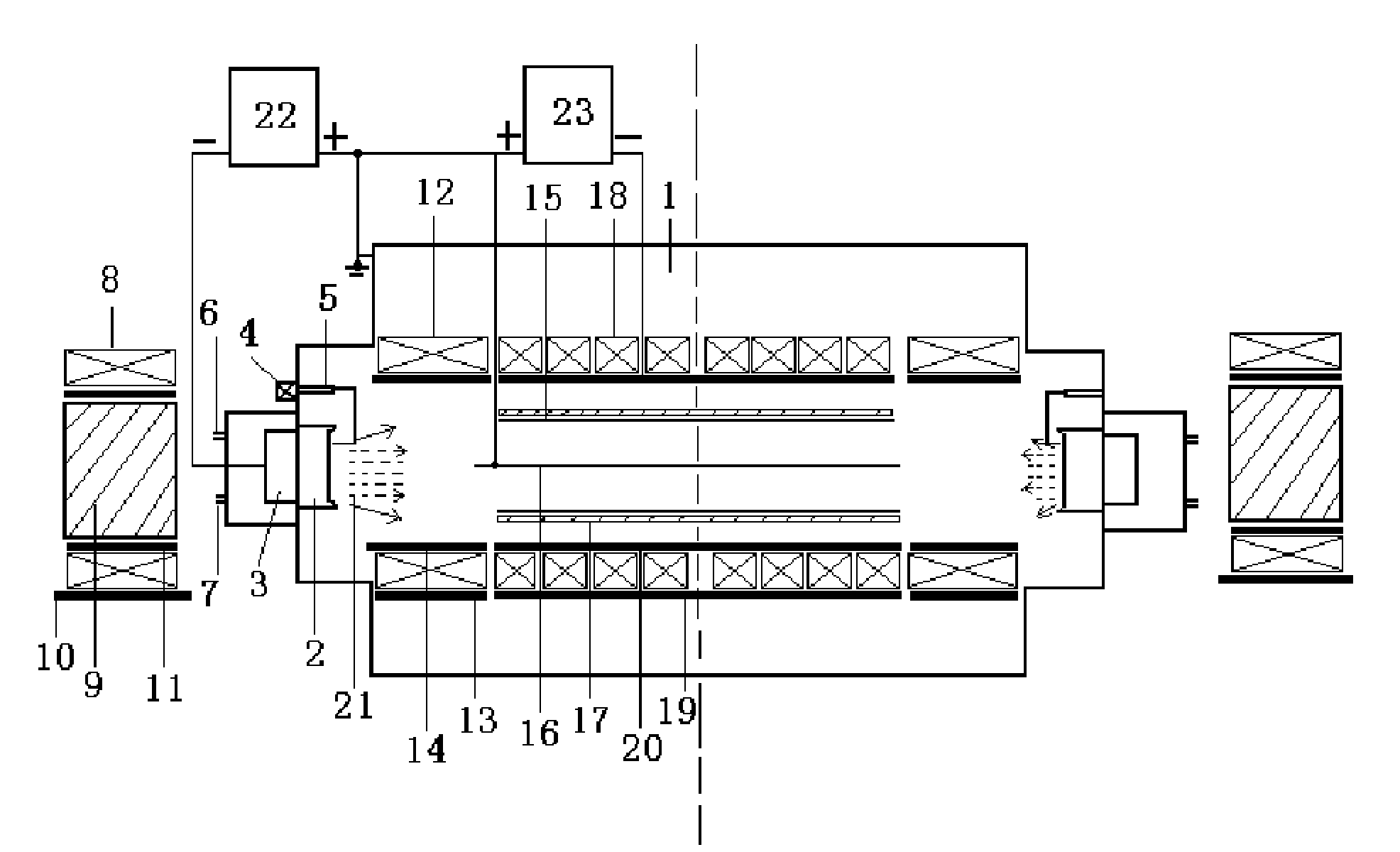
[0049] Such as image 3 As shown, the difference from Example 1 is that for through-hole long tubes or deep hole devices, a symmetrical magnetic field device structure and a cathode target structure are used to simultaneously protect the inner surface of the tube and modify the film or coating from both ends of the hole. layer, so that the length of the processed long tube can be doubled, three sets of magnetic field generators and cathode targets of the arc ion plating equipment in embodiment 1 are symmetrically provided with another three sets of magnetic field generators and cathode targets, and its structure The structure is the same as that of the three sets of magnetic field generating devices in Example 1, symmetrical structure, the symmetrical plane is the surface where the end of the third magnetic field generating device is located and is perpendicular to the workpiece, the symmetrical magnetic field structure and the cathode target structure are simultaneously carrie...

example 1

[0051] Example 1: Deposition of titanium nitride coating on the inner surface of stainless steel pipe

[0052] Adopt the equipment of embodiment 1, select the stainless steel pipe of Φ 14 * 300mm that the wall thickness is 3mm, put into the protective overcoat after dilute phosphoric acid cleaning, dehydrated alcohol ultrasonic cleaning, drying, put into the workpiece platform, make the stainless steel pipe The centerline coincides with the axis of the cathode target. The vacuum chamber is evacuated to 3×10 -3 After Pa, argon was introduced and the gas pressure in the vacuum chamber was maintained at 2.0Pa. Adjust the electromagnetic coil current of the first magnetic field generating device outside the vacuum chamber to 3.7A (corresponding to a magnetic induction of 3000Gauss); adjust the current of the bunching electromagnetic coil in the vacuum chamber, that is, the second magnetic field generating device to 2.1A (corresponding to a magnetic induction of 1000Gauss); adjust...


PUM

PropertyMeasurementUnit
Side lengthaaaaaaaaaa
Lengthaaaaaaaaaa
Lengthaaaaaaaaaa

Abstract

The invention relates to the field of film and coating preparation, and relates to an electric arc ion plating apparatus which is used for depositing a film or a coating on the inner surface of a long pipe or on the inner wall of a deep-hole device. The electric arc ion plating apparatus comprises three sets of magnetic field generation apparatuses. A first magnetic field generation apparatus used for beaming a metal ion flow emitted by a cathode target is arranged outside a vacuum chamber at a position corresponding to the back of the cathode target. A second magnetic field generation apparatus used for beaming the metal ion flow is arranged between the cathode target and a workpiece in the vacuum chamber. A third magnetic field generation apparatus used for diffusing the beamed metal ion flow and for making the metal ions move with a high speed towards the inner surface of the long pipe or the inner wall of the deep-hole device is arranged on the periphery of the workpiece in the vacuum chamber. The electric arc ion plating apparatus also comprises a pulse bias power supply used for further accelerating the metal ions moving towards the inner surface of the long pipe or the inner wall of the deep-hole device. With the apparatus provided by the invention, a technical problem for depositing a film or a coating on the inner surface of the long pipe or the inner wall of the deep-hole device is solved. Film or coating uniformity and quality are ensured, and the content of large particles in the deposited film or coating is reduced.

Description

technical field [0001] The invention relates to the field of thin film and coating preparation, in particular to an arc ion plating equipment for depositing thin film or coating on the inner surface of a long tube and the inner wall of a deep-hole device hole. Background technique [0002] In industrial applications, the inner surface of a large number of metal workpieces needs to be modified, especially for pipe fittings, the common treatment methods cannot meet the requirements for strengthening the inner surface. These workpieces often fail prematurely due to inner wall wear, corrosion, and oxidation. Therefore, the development of surface modification technologies and processes with wear resistance, corrosion resistance, and oxidation resistance is an urgent problem in the field of surface modification. [0003] For the modification of the inner wall of metal pipes, the earliest solution is to use electroplating and electroless plating processes. However, electroless pla...

Claims


Application Information

Patent Timeline
IPC IPC(8): C23C14/35C23C14/48
Inventor 杜昊赵彦辉肖金泉宋贵宏熊天英
Owner INST OF METAL RESEARCH - CHINESE ACAD OF SCI
Learn More