Wide output-range charge pump with active biasing current

Active Publication Date: 2005-09-01
AVAGO TECH INT SALES PTE LTD
View PDF8 Cites 44 Cited by
  • Summary
  • Abstract
  • Description
  • Claims
  • Application Information

AI Technical Summary

Benefits of technology

[0018] There is provided a charge pump circuit includes a charge pump having an output voltage. A replica circuit actively matches up and down currents in the charge pump to provide good jitter performance in a PLL. A charge pump bias current transistor biases the charge pump. The charge pump includes four transistors driven by differential UP and DOWN signals. The charge pump includes a first tail current source connected between a supply voltage and two of the four transistors that are driven by the differential UP signal, and a second tail current source connected between a supply voltage and the other two of the four transistors

Problems solved by technology

Therefore, any non-idealities in the charge pump due to IUP/IDOWN imbalance result in jitter in the PLL.
One of these non-idealities is DC offset, which occurs when the charge pump has unbalanced up and down currents IUP/IDOWN.
Since the output of the charge pump controls the VCO, the output frequency gets periodically disturbed

Method used


Image

  • Wide output-range charge pump with active biasing current
  • Wide output-range charge pump with active biasing current
  • Wide output-range charge pump with active biasing current

Examples


Example

[0024] Reference will now be made in detail to the preferred embodiments of the present invention, examples of which are illustrated in the accompanying drawings.

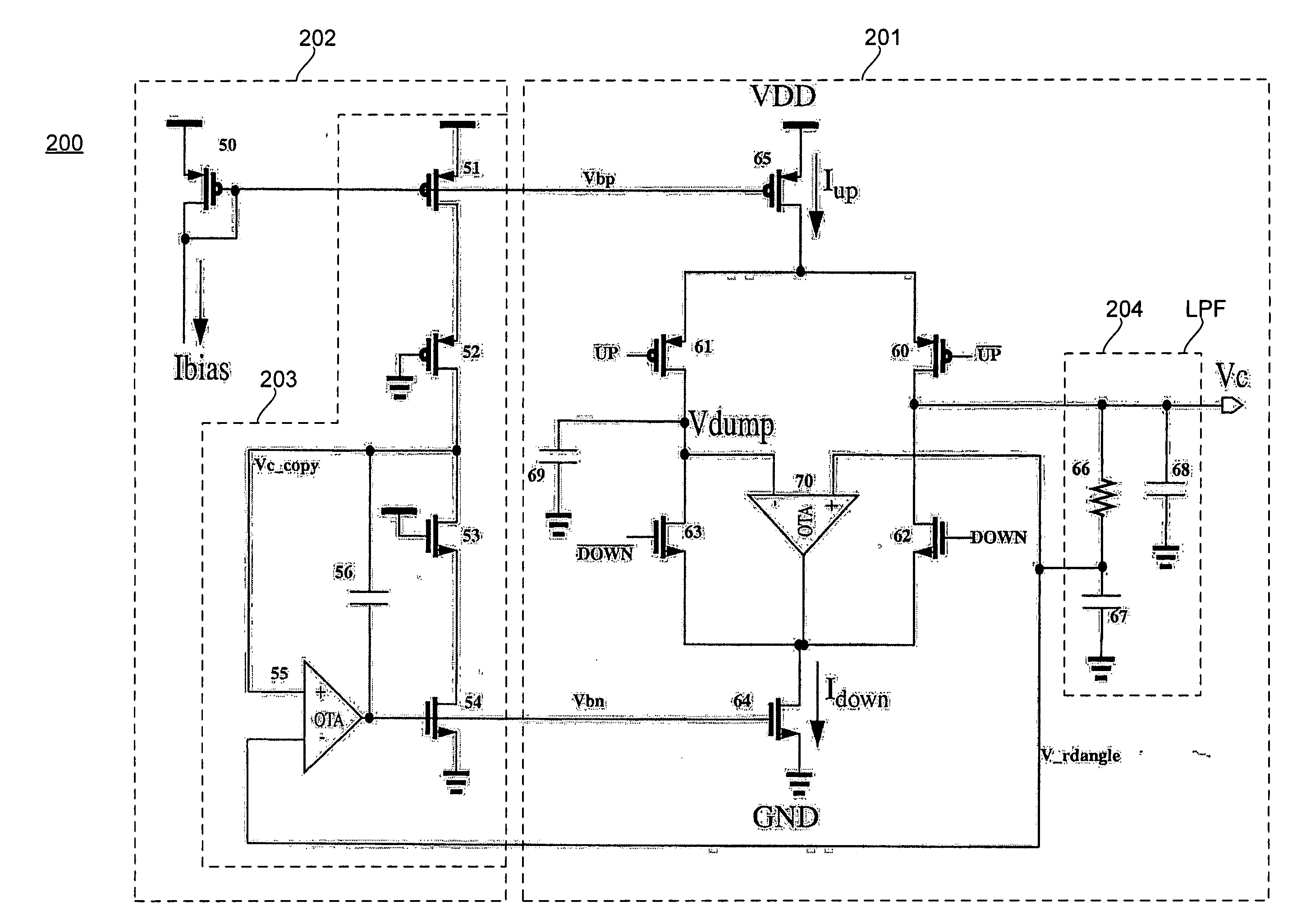
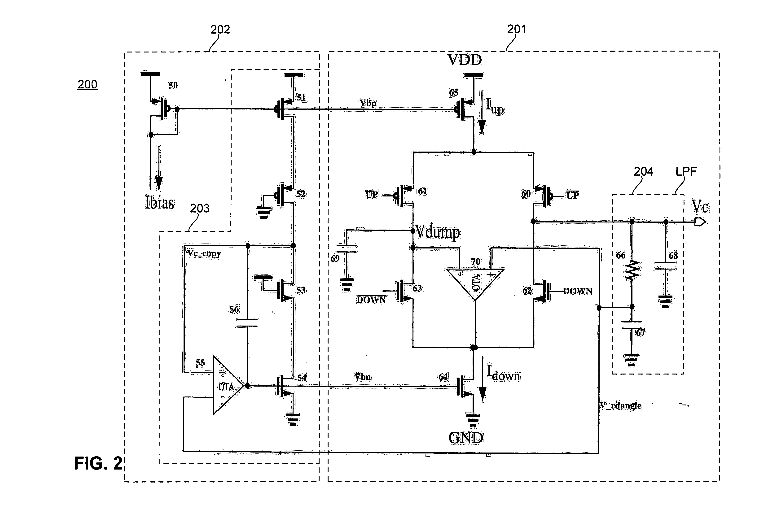
[0025] A charge pump with actively matched up and down currents IUP, IDOWN is described herein. An opamp and a replica circuit are applied to form a feedback loop to track the charge pump output voltage. With this feedback loop, the charge pump provides a low DC offset and an optimal transient response for a wide output range resulting in good jitter performance in a PLL. With the matching of up and down currents IUP, IDOWN, an output (pole) capacitor of the charge pump is charged and discharged identically.

[0026]FIG. 2 illustrates one embodiment of a charge pump circuit 200 of the present invention. It includes a bias replica circuit 202, including transistors 51, 52, 53, 54, an operational transconductance amplifier (OTA) 55 and a capacitor 56. An optional bias transistor 50 can be used to control voltage at a gate of t...


PUM


Abstract

A charge pump circuit includes a charge pump having an output voltage. A replica circuit actively matches up and down currents in the charge pump. A charge pump bias current transistor biases the charge pump. The charge pump includes four switches driven by differential UP and DOWN signals. The charge pump includes a first tail current source connected between a supply voltage and two of the four switches that are driven by the differential UP signal, and a second tail current source connected between a supply voltage and two of the four switches that are driven by the differential DOWN signal. The charge pump includes an operational amplifier whose output is connected to an output of one of the tail current sources. A dump capacitor is connected to a negative input of the operational amplifier. The replica circuit includes four transistors, two of which match the first and second tail current sources, and the other two match the switches driven by the differential UP and DOWN signals. The replica circuit includes a second operational amplifier that matches the charge up and down current for varied output voltage. A low pass filter is at the output voltage and includes a resistor-capacitor network.

Description

BACKGROUND OF THE INVENTION [0001] 1. Field of the Invention [0002] The present invention relates generally to charge pumps, and more particularly, to charge pumps used in phase locked loops. [0003] 2. Background Art [0004] Phase locking was invented in the 1930s, and is widely used in the electronics and communication systems. A Phase Locked Loop (PLL) can be used to synthesize new clocks by multiplication from input frequency. A PLL can also be used to suppress fast jitter, or to reduce timing skew between data and clock. [0005] In recent years, with the development of VLSI technologies, PLLs have finally been integrated on a chip without external components. This significantly reduces their cost, and enables more applications with enhanced performance and more features. [0006] For PLLs, jitter is an important parameter. It is observed at the crossing point of the clock waveform. Jitter is the time difference by which the PLL deviates from an ideal crossing point. Low-jitter PLLs ...

Claims


Application Information

Patent Timeline
IPC IPC(8): H03L7/06H03L7/089
CPCH03L7/0896
Inventor LI, NING
Owner AVAGO TECH INT SALES PTE LTD
Why Eureka
Try Eureka