Fluid transportation system, method for setting discharge amound of fluid

a fluid transportation system and fluid discharge technology, applied in the direction of positive displacement liquid engines, machines/engines, intravenous devices, etc., can solve the problems of complicated procedures, blockage of fluid flow, and handling of the system, and achieve the effect of stable fluid flow and simple structur

Inactive Publication Date: 2007-06-07
SEIKO EPSON CORP
View PDF12 Cites 24 Cited by
  • Summary
  • Abstract
  • Description
  • Claims
  • Application Information

AI Technical Summary

Benefits of technology

[0031] Since the tube guide securely returns the closed and deformed tube to the position of the initial condition, stable flow of fluid can be maintained.
[0032] Moreover, this function can be provided by a simple structure without requiring additional components.

Problems solved by technology

Thus, complicated procedures are required before, starting operation of the system.
In addition, the tube needs to be inserted into the main body in advance when the fluid transportation system is attached to other equipment or installed at a place where handling of the system is difficult.
In this case, flow of fluid is blocked or a predetermined flow amount of fluid is not secured.

Method used


Image

  • Fluid transportation system, method for setting discharge amound of fluid
  • Fluid transportation system, method for setting discharge amound of fluid
  • Fluid transportation system, method for setting discharge amound of fluid

Examples


Embodiment Construction

[0042] A preferred embodiment according to the invention is hereinafter described with reference to the drawings.

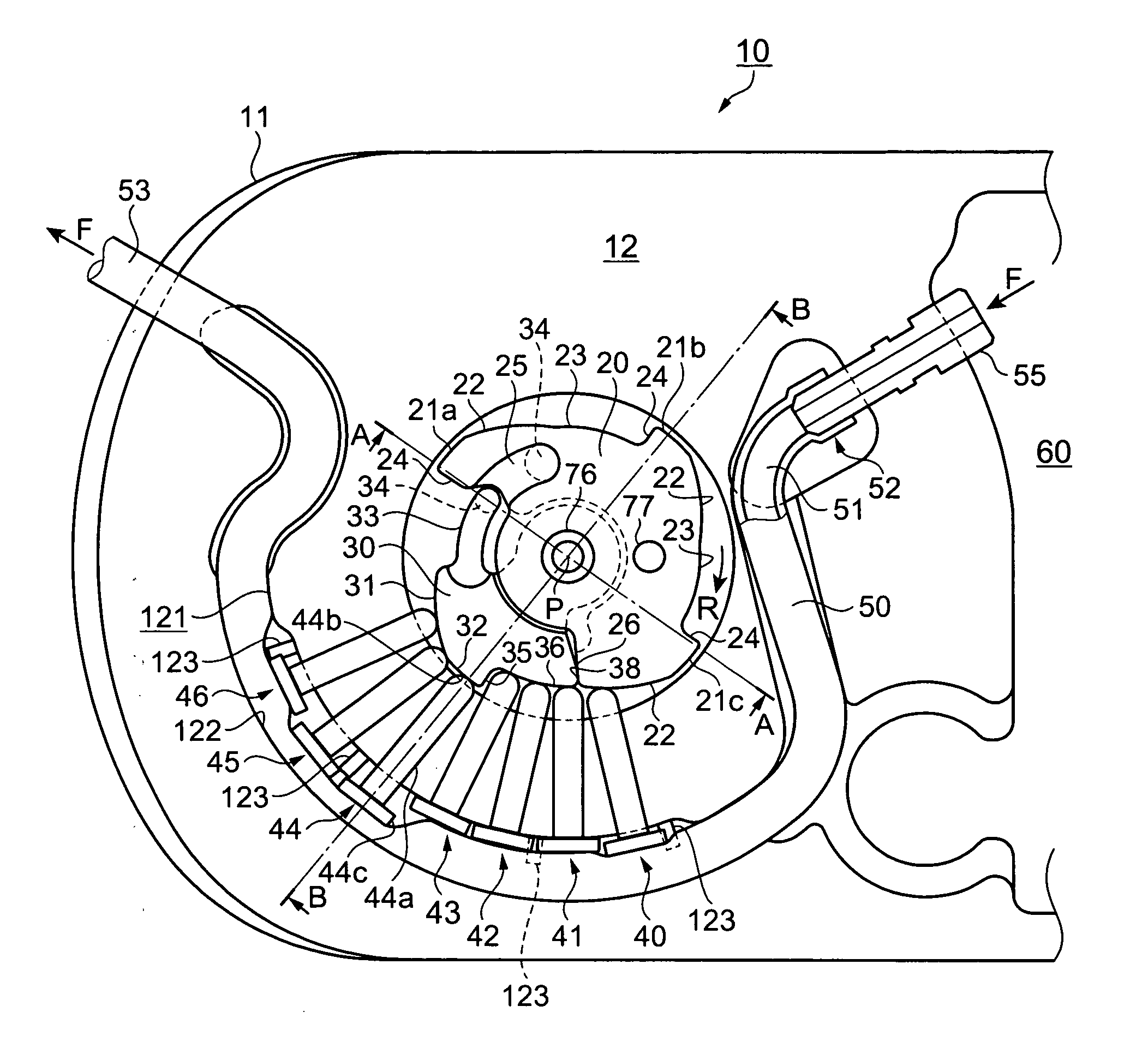
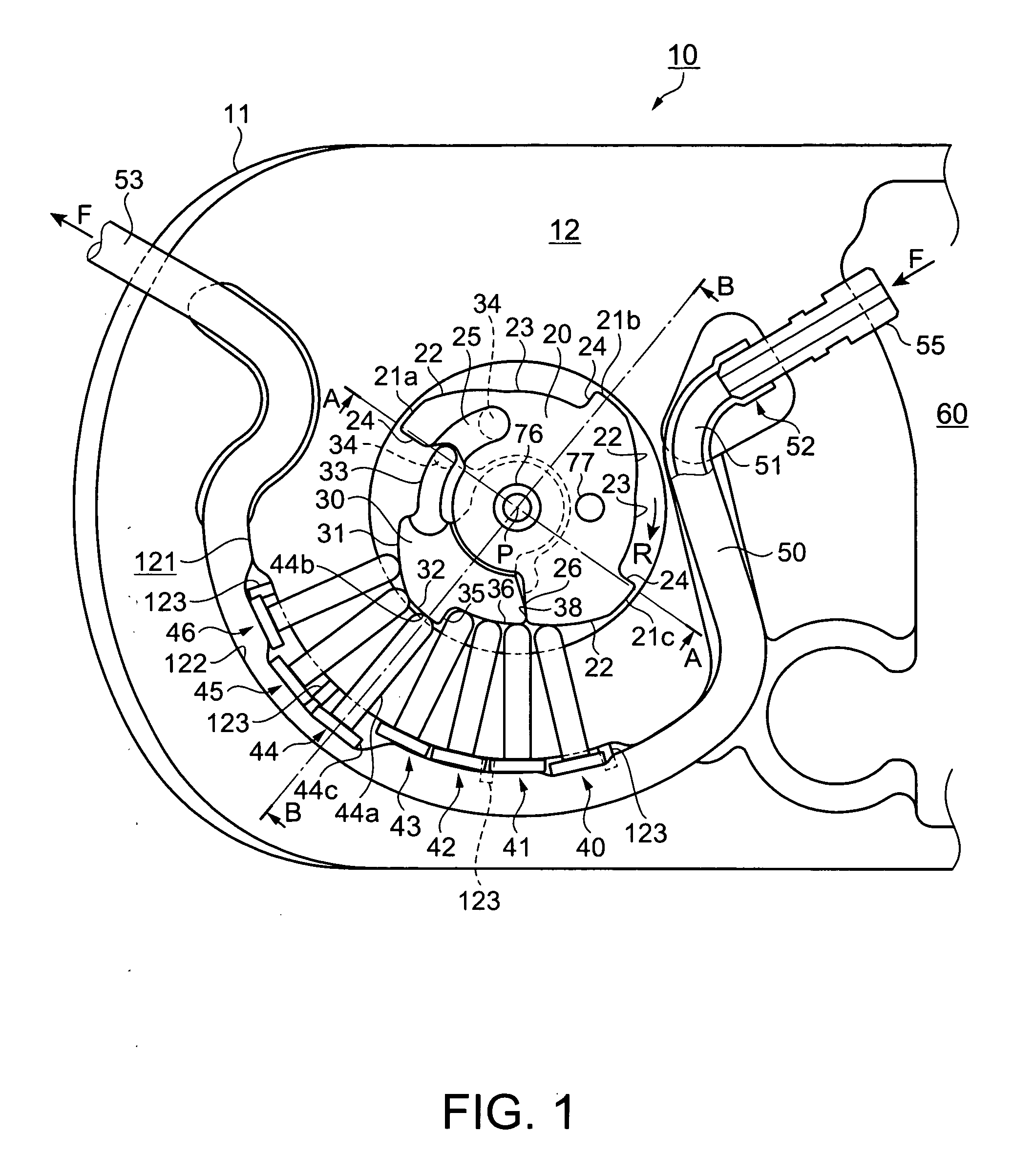
[0043]FIGS. 1 through 9 illustrate a fluid transportation system in an embodiment according to the invention. FIGS. 1 through 4 are a plan view and cross-sectional views of the fluid transportation system. FIGS. 5 through 9 are plan views and cross-sectional views showing conditions of the fluid transportation system during operation.

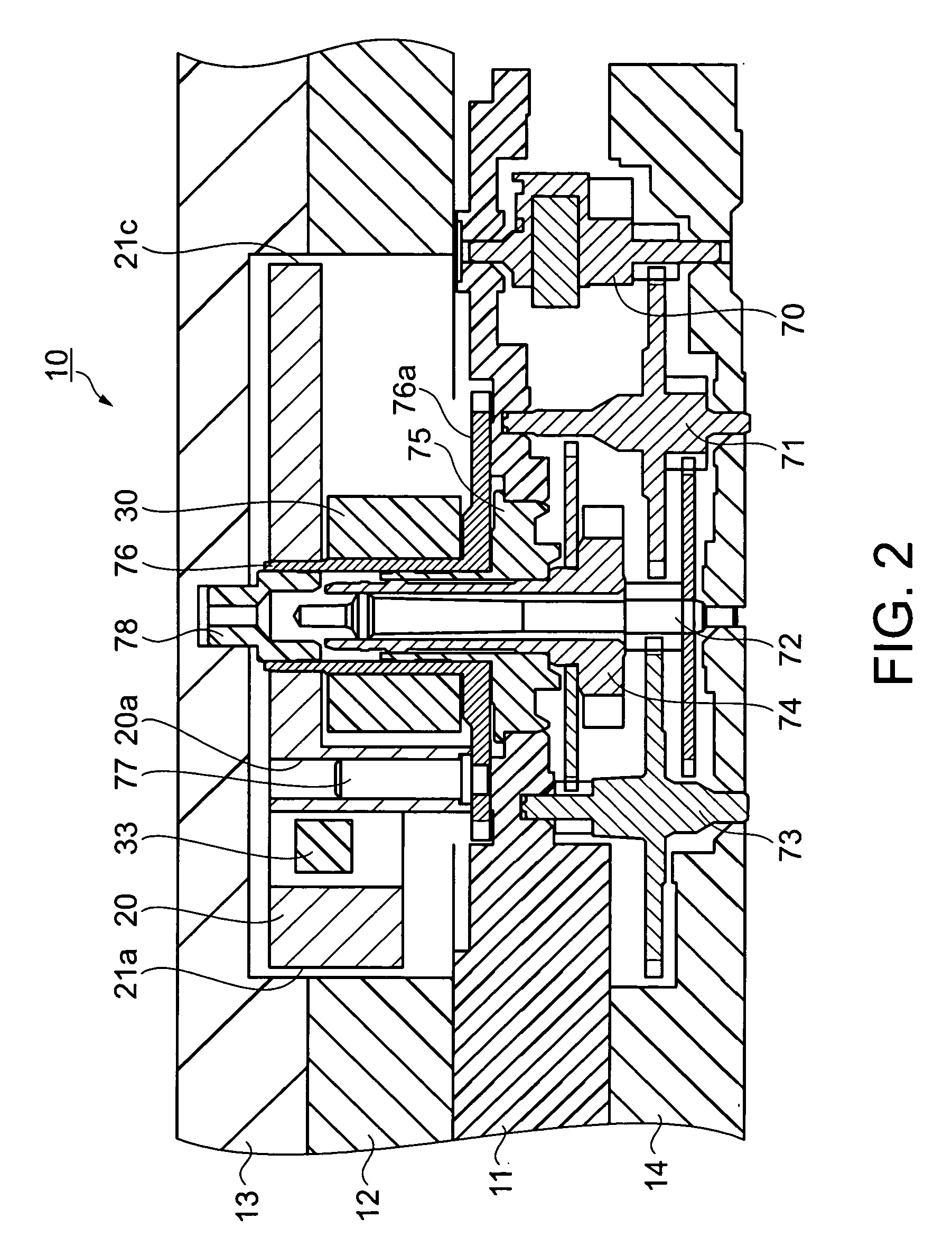
[0044]FIG. 1 is a plan view illustrating a part of the fluid transportation system in the embodiment. FIG. 2 is a partial cross-sectional view taken along a line A-A in FIG. 1. FIG. 3 is a partial cross-sectional view taken along a line B-B in FIG. 1. FIG. 4 is a cross-sectional view taken along a line D-D in FIG. 3. FIGS. 1 through 4 show a state in a second condition where a fluid transportation system 10 normally operates.

[0045] A structure of the fluid transportation system 10 in this embodiment is now described with reference to FIGS....


PUM


Abstract

A fluid transportation system includes an elastic tube, a tube frame to which the tube is attached such that the tube forms a circular arc, a first cam and a second cam disposed inside the tube, and fingers which radially extend from a rotation center in the space between the tube and the first and second cams. The first and second cams produce a first condition where the fingers are all released and a second condition where at least one of the fingers constantly closes the tube. The first and second cams sequentially press the fingers, and the fingers sequentially repeat closure and release of the tube so that fluid can continuously flow.

Description

BACKGROUND [0001] 1. Field of the Invention [0002] The present invention relates to a fluid transportation system, and more particularly to a structure of a fluid transportation system which presses an elastic tube by a plurality of fingers in accordance with rotation of cams so as to cause fluid to flow by sequentially closing and releasing the tube. [0003] 2. Background of the Invention [0004] A known fluid transportation system (pump) has a tube disposed along a curved and concaved compressed panel and a cam disposed in the vicinity of the compressed panel and the tube. A plurality of fingers are interposed between the cam and the tube. The plural fingers, which are sequentially pressed toward the tube in accordance with the rotation of the cam, compress the tube so as to cause fluid to flow. According to this fluid transportation system, a condition where fluid is caused to flow is produced by attaching the compressed panel to a main body (for example, see Patent Reference No. 1...

Claims


Application Information

Patent Timeline
Patent Type & Authority Applications(United States)
IPC IPC(8): F04B43/08
CPCA61M5/14228F04B43/082
Inventor MIYAZAKI, HAJIMEMIYASAKA, MAMORUKAZUO, KAWASUMI
Owner SEIKO EPSON CORP
Why Eureka
Try Eureka